楼主 #1 2019-05-23 10:51:24 分享评论
- guo_felix
- 会员
- 注册时间: 2018-04-12
- 已发帖子: 21
- 积分: 21
请教一下关于lichee nano在官网上电容屏的适配
底板 电容屏也是官网的 gt911
大概步骤就是在dtsi中(soc,pio节点)加节点 然后在dts中引用 http://nano.lichee.pro/build_sys/devicetree.html#id5
内核中已经勾选Gooddix I2C touchscreen ,启动log会报如下信息:
[    0.663532] i2c /dev entries driver
[    2.881100] i2c i2c-0: mv64xxx: I2C bus locked, block: 1, time_left: 0
[    2.887655] Goodix-TS 0-0014: i2c test failed attempt 1: -110
[    5.041092] i2c i2c-0: mv64xxx: I2C bus locked, block: 1, time_left: 0
[    5.047634] Goodix-TS 0-0014: i2c test failed attempt 2: -110
[    5.091084] Goodix-TS 0-0014: I2C communication failure: -110
[    5.096951] Goodix-TS: probe of 0-0014 failed with error -110
i2cdetect -l 命令输出如下:
i2c-0 i2c mv64xxx_i2c adapter I2C adapteri2cdetect -r -y 0 输出如下:
# i2cdetect -r -y 0
     0  1  2  3  4  5  6  7  8  9  a  b  c  d  e  f
00:          [ 1116.081094] i2c i2c-0: mv64xxx: I2C bus locked, block: 1, time_left: 0
-- [ 1118.161097] i2c i2c-0: mv64xxx: I2C bus locked, block: 1, time_left: 0
i2cset 也是会报I2C bus locked。
看原理图底板应该是有上拉的
不知道有没有人遇到过同样的情况,是我dts改错了吗?
照这个情况是不是cpu根本就没发出i2c信号?
还是如果根本就没接上也会有这种情况?
离线
楼主 #3 2019-05-23 11:24:29 分享评论
- guo_felix
- 会员
- 注册时间: 2018-04-12
- 已发帖子: 21
- 积分: 21
Re: 请教一下关于lichee nano在官网上电容屏的适配
.dtsi soc节点添加:
https://whycan.cn/files/members/735/dtsi_i2c.jpg
.dtsi pio节点添加:
https://whycan.cn/files/members/735/dtsi_pio.jpg
.dts 添加引用
离线
楼主 #4 2019-05-23 11:27:54 分享评论
- guo_felix
- 会员
- 注册时间: 2018-04-12
- 已发帖子: 21
- 积分: 21
Re: 请教一下关于lichee nano在官网上电容屏的适配
用code全部贴上来会不会有点长?
离线
楼主 #6 2019-05-23 11:32:17 分享评论
- guo_felix
- 会员
- 注册时间: 2018-04-12
- 已发帖子: 21
- 积分: 21
Re: 请教一下关于lichee nano在官网上电容屏的适配
以下为 suniv.dtsi
// SPDX-License-Identifier: (GPL-2.0+ OR X11)
/*
 * Copyright 2018 Icenowy Zheng <icenowy@aosc.io>
 */

#include <dt-bindings/clock/suniv-ccu.h>
#include <dt-bindings/reset/suniv-ccu.h>

/ {
	#address-cells = <1>;
	#size-cells = <1>;
	interrupt-parent = <&intc>;

	clocks {
		#address-cells = <1>;
		#size-cells = <1>;
		ranges;

		osc24M: clk-24M {
			#clock-cells = <0>;
			compatible = "fixed-clock";
			clock-frequency = <24000000>;
			clock-output-names = "osc24M";
		};

		osc32k: clk-32k {
			#clock-cells = <0>;
			compatible = "fixed-clock";
			clock-frequency = <32768>;
			clock-output-names = "osc32k";
		};

		fake100M: clk-100M {
			#clock-cells = <0>;
			compatible = "fixed-clock";
			clock-frequency = <100000000>;
			clock-output-names = "fake-100M";
		};
	};

	cpus {
		#address-cells = <0>;
		#size-cells = <0>;

		cpu {
			compatible = "arm,arm926ej-s";
			device_type = "cpu";
		};
	};

	de: display-engine {
		compatible = "allwinner,suniv-display-engine";
		allwinner,pipelines = <&fe0>;
		status = "disabled";
	};

	soc {
		compatible = "simple-bus";
		#address-cells = <1>;
		#size-cells = <1>;
		ranges;

		sram-controller@1c00000 {
			compatible = "allwinner,sun4i-a10-sram-controller";
			reg = <0x01c00000 0x30>;
			#address-cells = <1>;
			#size-cells = <1>;
			ranges;

			sram_d: sram@10000 {
				compatible = "mmio-sram";
				reg = <0x00010000 0x1000>;
				#address-cells = <1>;
				#size-cells = <1>;
				ranges = <0 0x00010000 0x1000>;

				otg_sram: sram-section@0 {
					compatible = "allwinner,sun4i-a10-sram-d";
					reg = <0x0000 0x1000>;
					status = "disabled";
				};
			};
		};

		spi0: spi@1c05000 {
			compatible = "allwinner,suniv-spi",
				     "allwinner,sun8i-h3-spi";
			reg = <0x01c05000 0x1000>;
			interrupts = <10>;
			clocks = <&ccu CLK_BUS_SPI0>, <&ccu CLK_BUS_SPI0>;
			clock-names = "ahb", "mod";
			resets = <&ccu RST_BUS_SPI0>;
			status = "disabled";
			#address-cells = <1>;
			#size-cells = <0>;
		};

		spi1: spi@1c06000 {
			compatible = "allwinner,suniv-spi",
				     "allwinner,sun8i-h3-spi";
			reg = <0x01c06000 0x1000>;
			interrupts = <11>;
			clocks = <&ccu CLK_BUS_SPI1>, <&ccu CLK_BUS_SPI1>;
			clock-names = "ahb", "mod";
			resets = <&ccu RST_BUS_SPI1>;
			status = "disabled";
			#address-cells = <1>;
			#size-cells = <0>;
		};

		tcon0: lcd-controller@1c0c000 {
			compatible = "allwinner,suniv-tcon";
			reg = <0x01c0c000 0x1000>;
			interrupts = <29>;
			clocks = <&ccu CLK_BUS_LCD>,
				 <&ccu CLK_TCON>,
				 <&osc24M>;	/* Still unknown */
			clock-names = "ahb",
				      "tcon-ch0",
				      "tcon-ch1";
			clock-output-names = "tcon-pixel-clock";
			resets = <&ccu RST_BUS_LCD>;
			reset-names = "lcd";
			status = "disabled";

			ports {
				#address-cells = <1>;
				#size-cells = <0>;

				tcon0_in: port@0 {
					#address-cells = <1>;
					#size-cells = <0>;
					reg = <0>;

					tcon0_in_be0: endpoint@0 {
						reg = <0>;
						remote-endpoint = <&be0_out_tcon0>;
					};
				};

				tcon0_out: port@1 {
					#address-cells = <1>;
					#size-cells = <0>;
					reg = <1>;
				};
			};
		};

		mmc0: mmc@1c0f000 {
			compatible = "allwinner,suniv-mmc",
				     "allwinner,sun7i-a20-mmc";
			reg = <0x01c0f000 0x1000>;
			clocks = <&ccu CLK_BUS_MMC0>,
				 <&ccu CLK_MMC0>,
				 <&ccu CLK_MMC0_OUTPUT>,
				 <&ccu CLK_MMC0_SAMPLE>;
			clock-names = "ahb",
				      "mmc",
				      "output",
				      "sample";
			resets = <&ccu RST_BUS_MMC0>;
			reset-names = "ahb";
			interrupts = <23>;
			pinctrl-names = "default";
			pinctrl-0 = <&mmc0_pins>;
			status = "disabled";
			#address-cells = <1>;
			#size-cells = <0>;
		};

		mmc1: mmc@1c10000 {
			compatible = "allwinner,suniv-mmc",
				     "allwinner,sun7i-a20-mmc";
			reg = <0x01c10000 0x1000>;
			clocks = <&ccu CLK_BUS_MMC1>,
				 <&ccu CLK_MMC1>,
				 <&ccu CLK_MMC1_OUTPUT>,
				 <&ccu CLK_MMC1_SAMPLE>;
			clock-names = "ahb",
				      "mmc",
				      "output",
				      "sample";
			resets = <&ccu RST_BUS_MMC1>;
			reset-names = "ahb";
			interrupts = <24>;
			status = "disabled";
			#address-cells = <1>;
			#size-cells = <0>;
		};

		ccu: clock@1c20000 {
			compatible = "allwinner,suniv-ccu";
			reg = <0x01c20000 0x400>;
			clocks = <&osc24M>, <&osc32k>;
			clock-names = "hosc", "losc";
			#clock-cells = <1>;
			#reset-cells = <1>;
		};

		intc: interrupt-controller@1c20400 {
			compatible = "allwinner,suniv-ic";
			reg = <0x01c20400 0x400>;
			interrupt-controller;
			#interrupt-cells = <1>;
		};

		pio: pinctrl@1c20800 {
			compatible = "allwinner,suniv-pinctrl";
			reg = <0x01c20800 0x400>;
			interrupts = <38>, <39>, <40>;
			clocks = <&ccu CLK_BUS_PIO>, <&osc24M>, <&osc32k>;
			clock-names = "apb", "hosc", "losc";
			gpio-controller;
			interrupt-controller;
			#interrupt-cells = <3>;
			#gpio-cells = <3>;

			spi0_pins_a: spi0-pins-pc {
				pins = "PC0", "PC1", "PC2", "PC3";
				function = "spi0";
			};

			lcd_rgb666_pins: lcd-rgb666-pins {
				pins = "PD1", "PD2", "PD3", "PD4",
				       "PD5", "PD6", "PD7", "PD8", "PD9",
				       "PD10", "PD11", "PD13", "PD14",
				       "PD15", "PD16", "PD17", "PD18", "PD19",
				       "PD20", "PD21";
				function = "lcd";
			};

			uart0_pins_a: uart-pins-pe {
				pins = "PE0", "PE1";
				function = "uart0";
			};

			uart2_pins_a: uart2-pins-pe {
				pins = "PE7", "PE8";
				function = "uart2";
			};

			mmc0_pins: mmc0-pins {
				pins = "PF0", "PF1", "PF2", "PF3", "PF4", "PF5";
				function = "mmc0";
			};
			i2c0_pins: i2c0 {
				pins = "PE11", "PE12";
				function = "i2c0";
			};

		};

		timer@1c20c00 {
			compatible = "allwinner,suniv-timer";
			reg = <0x01c20c00 0x90>;
			interrupts = <13>;
			clocks = <&osc24M>;
		};

		wdt: watchdog@1c20ca0 {
			compatible = "allwinner,sun6i-a31-wdt";
			reg = <0x01c20ca0 0x20>;
		};

		uart0: serial@1c25000 {
			compatible = "snps,dw-apb-uart";
			reg = <0x01c25000 0x400>;
			interrupts = <1>;
			reg-shift = <2>;
			reg-io-width = <4>;
			clocks = <&ccu CLK_BUS_UART0>;
			resets = <&ccu RST_BUS_UART0>;
			status = "disabled";
		};

		uart1: serial@1c25400 {
			compatible = "snps,dw-apb-uart";
			reg = <0x01c25400 0x400>;
			interrupts = <2>;
			reg-shift = <2>;
			reg-io-width = <4>;
			clocks = <&ccu CLK_BUS_UART1>;
			resets = <&ccu RST_BUS_UART1>;
			status = "disabled";
		};

		uart2: serial@1c25800 {
			compatible = "snps,dw-apb-uart";
			reg = <0x01c25800 0x400>;
			interrupts = <3>;
			reg-shift = <2>;
			reg-io-width = <4>;
			clocks = <&ccu CLK_BUS_UART2>;
			resets = <&ccu RST_BUS_UART2>;
			status = "disabled";
		};

		usb_otg: usb@1c13000 {
			compatible = "allwinner,suniv-musb";
			reg = <0x01c13000 0x0400>;
			clocks = <&ccu CLK_BUS_OTG>;
			resets = <&ccu RST_BUS_OTG>;
			interrupts = <26>;
			interrupt-names = "mc";
			phys = <&usbphy 0>;
			phy-names = "usb";
			extcon = <&usbphy 0>;
			allwinner,sram = <&otg_sram 1>;
			status = "disabled";
		};

		usbphy: phy@1c13400 {
			compatible = "allwinner,suniv-usb-phy";
			reg = <0x01c13400 0x10>;
			reg-names = "phy_ctrl";
			clocks = <&ccu CLK_USB_PHY0>;
			clock-names = "usb0_phy";
			resets = <&ccu RST_USB_PHY0>;
			reset-names = "usb0_reset";
			#phy-cells = <1>;
			status = "disabled";
		};

		fe0: display-frontend@1e00000 {
			compatible = "allwinner,suniv-display-frontend";
			reg = <0x01e00000 0x20000>;
			interrupts = <30>;
			clocks = <&ccu CLK_BUS_DE_FE>, <&ccu CLK_DE_FE>,
				 <&ccu CLK_DRAM_DE_FE>;
			clock-names = "ahb", "mod",
				      "ram";
			resets = <&ccu RST_BUS_DE_FE>;
			status = "disabled";

			ports {
				#address-cells = <1>;
				#size-cells = <0>;

				fe0_out: port@1 {
					#address-cells = <1>;
					#size-cells = <0>;
					reg = <1>;

					fe0_out_be0: endpoint@0 {
						reg = <0>;
						remote-endpoint = <&be0_in_fe0>;
					};
				};
			};
		};

		be0: display-backend@1e60000 {
			compatible = "allwinner,suniv-display-backend";
			reg = <0x01e60000 0x10000>;
			reg-names = "be";
			interrupts = <31>;
			clocks = <&ccu CLK_BUS_DE_BE>, <&ccu CLK_DE_BE>,
				 <&ccu CLK_DRAM_DE_BE>;
			clock-names = "ahb", "mod",
				      "ram";
			resets = <&ccu RST_BUS_DE_BE>;
			reset-names = "be";
			assigned-clocks = <&ccu CLK_DE_BE>;
			assigned-clock-rates = <300000000>;

			ports {
				#address-cells = <1>;
				#size-cells = <0>;

				be0_in: port@0 {
					#address-cells = <1>;
					#size-cells = <0>;
					reg = <0>;

					be0_in_fe0: endpoint@0 {
						reg = <0>;
						remote-endpoint = <&fe0_out_be0>;
					};
				};

				be0_out: port@1 {
					#address-cells = <1>;
					#size-cells = <0>;
					reg = <1>;

					be0_out_tcon0: endpoint@0 {
						reg = <0>;
						remote-endpoint = <&tcon0_in_be0>;
					};
				};
			};
		};

		i2c0: i2c@1C27000{

					compatible = "allwinner,sun6i-a31-i2c";
					reg = <0x01c27000 0x400>;
					interrupts = <7>;
					clocks = <&ccu CLK_BUS_I2C0>;
					resets = <&ccu RST_BUS_I2C0>;
					pinctrl-names = "default";
					pinctrl-0 = <&i2c0_pins>;
					status = "disabled";
					#address-cells = <1>;
					#size-cells = <0>;

				};

	};
};
以下为 suniv-f1c100s-licheepi-nano.dts:
// SPDX-License-Identifier: (GPL-2.0+ OR X11)
/*
* Copyright 2018 Icenowy Zheng <icenowy@aosc.io>
*/
/dts-v1/;
#include "suniv-f1c100s.dtsi"
#include <dt-bindings/gpio/gpio.h>
// touch screen
#include <dt-bindings/input/input.h>
#include <dt-bindings/interrupt-controller/irq.h>
/ {
model = "Lichee Pi Nano";
compatible = "licheepi,licheepi-nano", "allwinner,suniv-f1c100s",
"allwinner,suniv";
aliases {
serial0 = &uart0;
spi0 = &spi0;
};
chosen {
stdout-path = "serial0:115200n8";
};
panel: panel {
compatible = "lg,lb070wv8", "simple-panel";
#address-cells = <1>;
#size-cells = <0>;
enable-gpios = <&pio 4 5 GPIO_ACTIVE_HIGH>;
port@0 {
reg = <0>;
#address-cells = <1>;
#size-cells = <0>;
panel_input: endpoint@0 {
reg = <0>;
remote-endpoint = <&tcon0_out_lcd>;
};
};
};
reg_vcc3v3: vcc3v3 {
compatible = "regulator-fixed";
regulator-name = "vcc3v3";
regulator-min-microvolt = <3300000>;
regulator-max-microvolt = <3300000>;
};
};
&de {
status = "okay";
};
&mmc0 {
vmmc-supply = <®_vcc3v3>;
bus-width = <4>;
broken-cd;
status = "okay";
};
&otg_sram {
status = "okay";
};
&spi0 {
pinctrl-names = "default";
pinctrl-0 = <&spi0_pins_a>;
status = "okay";
flash@0 {
#address-cells = <1>;
#size-cells = <1>;
compatible = "winbond,w25q128", "jedec,spi-nor";
reg = <0>;
spi-max-frequency = <40000000>;
};
};
&tcon0 {
pinctrl-names = "default";
pinctrl-0 = <&lcd_rgb666_pins>;
status = "okay";
};
&tcon0_out {
tcon0_out_lcd: endpoint@0 {
reg = <0>;
remote-endpoint = <&panel_input>;
};
};
&uart0 {
pinctrl-names = "default";
pinctrl-0 = <&uart0_pins_a>;
status = "okay";
};
&uart2 {
pinctrl-names = "default";
pinctrl-0 = <&uart2_pins_a>;
status = "okay";
};
&usb_otg {
dr_mode = "otg";
status = "okay";
};
&usbphy {
usb0_id_det-gpio = <&pio 4 2 GPIO_ACTIVE_HIGH>; /* PE2 */
status = "okay";
};
&i2c0{
pinctrl-0 = <&i2c0_pins>;
pinctrl-names = "default";
status = "okay";
gt911:touchscreen@14{
compatible = "goodix,gt911";
reg = <0x14>;
interrupt-parent = <&pio>;
interrupts = <4 10 IRQ_TYPE_EDGE_FALLING>;/*(PE10)*/
pinctrl-names = "default";
pinctrl-0 = <&ts_reset_pin>;
irq-gpios = <&pio 4 10 GPIO_ACTIVE_HIGH>;/*(PE10>*/
reset-gpios = <&pio 4 9 GPIO_ACTIVE_HIGH>; /*RST (PE9)*/
/*touchscreen-swapped-x-y*/
};
};
&pio {
ts_reset_pin:ts_reset_pin@0{
pins = "PE9";
function = "gpio_out";
};
};最近编辑记录 guo_felix (2019-05-23 11:34:01)
离线
楼主 #7 2019-05-23 11:33:47 分享评论
- guo_felix
- 会员
- 注册时间: 2018-04-12
- 已发帖子: 21
- 积分: 21
Re: 请教一下关于lichee nano在官网上电容屏的适配
尝试了一下 确实是 我以为不会自适应宽度 想多了
离线
#8 2019-05-23 11:51:42 分享评论
- 晕哥
- 管理员
- 所在地: 微信 whycan_cn
- 注册时间: 2017-09-06
- 已发帖子: 9,236
- 积分: 9197
离线
楼主 #9 2019-05-23 15:44:59 分享评论
- guo_felix
- 会员
- 注册时间: 2018-04-12
- 已发帖子: 21
- 积分: 21
Re: 请教一下关于lichee nano在官网上电容屏的适配
谢谢晕哥 之前一直怀疑设备树写得有问题 检测了好几遍,也确实检查出了问题。后来尝试控制PE11 和PE12,发现抓从底板上引出来的PE12没办法拉低,但cat value 又确实是0,最后发现是核心板和底板就这个脚虚焊了 现在i2cdetect:
# i2cdetect -y -r 0
     0  1  2  3  4  5  6  7  8  9  a  b  c  d  e  f
00:          -- -- -- -- -- -- -- -- -- -- -- -- --
10: -- -- -- -- -- -- -- -- -- -- -- -- -- -- -- --
20: -- -- -- -- -- -- -- -- -- -- -- -- -- -- -- --
30: -- -- -- -- -- -- -- -- -- -- -- -- -- -- -- --
40: -- -- -- -- -- -- -- -- -- -- -- -- -- -- -- --
50: -- -- -- -- -- -- -- -- -- -- -- -- -- 5d -- --
60: -- -- -- -- -- -- -- -- -- -- -- -- -- -- -- --
70: -- -- -- -- -- -- -- --
虽然log中好像关于触屏的驱动还是有问题:
[    0.663484] i2c /dev entries driver
[    0.781273] Goodix-TS 0-0014: i2c test failed attempt 1: -6
[    0.821241] Goodix-TS 0-0014: i2c test failed attempt 2: -6
[    0.861061] Goodix-TS 0-0014: I2C communication failure: -6
但至少I2c是没问题的了
离线
楼主 #10 2019-05-23 16:28:33 分享评论
- guo_felix
- 会员
- 注册时间: 2018-04-12
- 已发帖子: 21
- 积分: 21
Re: 请教一下关于lichee nano在官网上电容屏的适配
注意到原理图中 电容屏中断口连接的是PE3?
而且实际复位端口也是直接用了RC,即图中1口,实际dts并没有配置到gt911的中断端口以及复位端口?
尝试如下修改,不过好像没什么用处:
	gt911:touchscreen@14{
		compatible = "goodix,gt911";
		reg = <0x14>;
		interrupt-parent = <&pio>;
		interrupts = <4 3 IRQ_TYPE_EDGE_FALLING>;/*(PE3)*/
		pinctrl-names = "default";
		pinctrl-0 = <&ts_reset_pin>;
		irq-gpios = <&pio 4 3 GPIO_ACTIVE_HIGH>;/*(PE3)*/
		reset-gpios = <&pio 4 9 GPIO_ACTIVE_HIGH>; /*RST (PE9)*/
		/*touchscreen-swapped-x-y*/
		};
还想请问一下,如果中断配置成功的话,是不是/dev/下就会有input文件夹,因为现在板上一直是没有这个文件夹
最近编辑记录 guo_felix (2019-05-23 16:31:04)
离线
楼主 #12 2019-05-23 22:33:53 分享评论
- guo_felix
- 会员
- 注册时间: 2018-04-12
- 已发帖子: 21
- 积分: 21
Re: 请教一下关于lichee nano在官网上电容屏的适配
谢谢晕哥 已经可以了,可以读到gt911,可以运行 ts_test
[    0.663190] i2c /dev entries driver
[    0.782659] Goodix-TS 0-005d: ID 911, version: 1060
[    0.790639] Goodix-TS 0-005d: Direct firmware load for goodix_911_cfg.bin failed with error -2
总结一下,应该是需要dts将引脚改对(PE3),还有就是<reg>也要改到相应0x5d
离线
楼主 #13 2019-05-24 11:30:24 分享评论
- guo_felix
- 会员
- 注册时间: 2018-04-12
- 已发帖子: 21
- 积分: 21
Re: 请教一下关于lichee nano在官网上电容屏的适配
运行ts_calibrate 也没有问题,可以成功校准,但是只相对于tslib来说有校准,对于littlevgl直接读取/input/event的时候触屏还是会有问题。
在网上看到有方法改写 evdev.c中的几个读取函数,用tslib来实现,这样就可以利用到运行test_calibrate得到的参数。
具体方法如下网址:
[笔记]在嵌入式linux上运行LittlevGL GUI demo 支持tslib(出处: amoBBS 阿莫电子论坛)
实际就是改evdev_init 以及 evdev_read两个函数
算是分享一下和官网上不同的校准方式吧
离线
#14 2019-11-25 22:14:05 分享评论
- xd717
- 会员
- 注册时间: 2019-10-23
- 已发帖子: 51
- 积分: 51
Re: 请教一下关于lichee nano在官网上电容屏的适配
底板 电容屏也是官网的 gt911
大概步骤就是在dtsi中(soc,pio节点)加节点 然后在dts中引用 http://nano.lichee.pro/build_sys/devicetree.html#id5
内核中已经勾选Gooddix I2C touchscreen ,启动log会报如下信息:
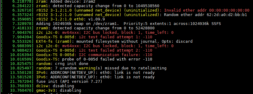
[    0.663532] i2c /dev entries driver
[    2.881100] i2c i2c-0: mv64xxx: I2C bus locked, block: 1, time_left: 0
[    2.887655] Goodix-TS 0-0014: i2c test failed attempt 1: -110
[    5.041092] i2c i2c-0: mv64xxx: I2C bus locked, block: 1, time_left: 0
[    5.047634] Goodix-TS 0-0014: i2c test failed attempt 2: -110
[    5.091084] Goodix-TS 0-0014: I2C communication failure: -110
[    5.096951] Goodix-TS: probe of 0-0014 failed with error -110
i2cdetect -l 命令输出如下:
i2c-0 i2c mv64xxx_i2c adapter I2C adapteri2cdetect -r -y 0 输出如下:
# i2cdetect -r -y 0
     0  1  2  3  4  5  6  7  8  9  a  b  c  d  e  f
00:          [ 1116.081094] i2c i2c-0: mv64xxx: I2C bus locked, block: 1, time_left: 0
-- [ 1118.161097] i2c i2c-0: mv64xxx: I2C bus locked, block: 1, time_left: 0
i2cset 也是会报I2C bus locked。
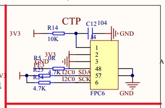
看原理图底板应该是有上拉的
https://whycan.cn/files/members/735/ts_i2c.jpg
不知道有没有人遇到过同样的情况,是我dts改错了吗?
照这个情况是不是cpu根本就没发出i2c信号?
还是如果根本就没接上也会有这种情况?
我的板子原理图是这样的 按照你这个配法 也跟你一开始问题一样 ,引脚编号都对应好了 dts是按你这样去改引脚的 但还是不行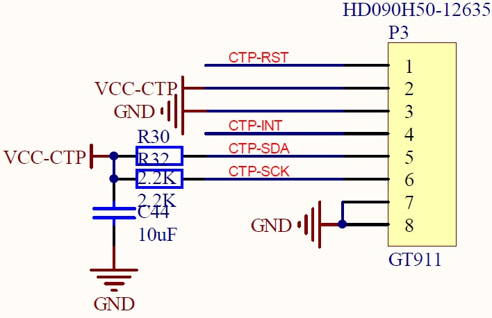
拜托帮忙看看
离线
#15 2019-11-25 22:14:37 分享评论
- xd717
- 会员
- 注册时间: 2019-10-23
- 已发帖子: 51
- 积分: 51
Re: 请教一下关于lichee nano在官网上电容屏的适配
没有 /dev/eventX 说明配置或者软件硬件还是有问题,看下启动log,上面有提示有没有成功
晕哥帮忙看看
离线
#17 2019-11-25 22:25:41 分享评论
- xd717
- 会员
- 注册时间: 2019-10-23
- 已发帖子: 51
- 积分: 51
Re: 请教一下关于lichee nano在官网上电容屏的适配
log发出来看下
离线
#18 2019-11-25 22:28:20 分享评论
- xd717
- 会员
- 注册时间: 2019-10-23
- 已发帖子: 51
- 积分: 51
Re: 请教一下关于lichee nano在官网上电容屏的适配
log发出来看下
dts 相关信息:
i2c0_pins: i2c0-pins {
pins = "PH0", "PH1";
function = "i2c0";
};
i2c0: i2c@1c2ac00 {
compatible = "allwinner,sun6i-a31-i2c";
reg = <0x01c2ac00 0x400>;
interrupts = <GIC_SPI 7 IRQ_TYPE_LEVEL_HIGH>;
clocks = <&ccu CLK_BUS_I2C0>;
resets = <&ccu RST_BUS_I2C0>;
pinctrl-names = "default";
pinctrl-0 = <&i2c0_pins>;
status = "disabled";
#address-cells = <1>;
#size-cells = <0>;
};
&i2c0{
pinctrl-0 = <&i2c0_pins>;
pinctrl-names = "default";
status = "okay";
gt911:touchscreen@5d{
compatible = "goodix,gt911";
reg = <0x5d>; /*0x14*/
interrupt-parent = <&pio>;
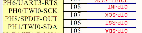
interrupts = <7 6 IRQ_TYPE_EDGE_FALLING>;/*(PH6)*/
pinctrl-names = "default";
pinctrl-0 = <&ts_reset_pin>;
irq-gpios = <&pio 7 6 GPIO_ACTIVE_HIGH>;/*(PH6>*/
reset-gpios = <&pio 7 8 GPIO_ACTIVE_HIGH>; /*RST (PH8)*/
/*touchscreen-swapped-x-y*/
};
};
&pio {
ts_reset_pin:ts_reset_pin@0{
pins = "PH8";
function = "gpio_out";
};
};
这样配有啥问题吗
离线
#20 2019-11-25 22:55:15 分享评论
- xd717
- 会员
- 注册时间: 2019-10-23
- 已发帖子: 51
- 积分: 51
Re: 请教一下关于lichee nano在官网上电容屏的适配
i2c的scl/sda两个引脚有没有上拉?
软件上拉?没有诶 这两个引脚上拉没有配
离线
#22 2019-11-25 23:42:45 分享评论
- xd717
- 会员
- 注册时间: 2019-10-23
- 已发帖子: 51
- 积分: 51
Re: 请教一下关于lichee nano在官网上电容屏的适配
用10k-47k 电阻上拉到 3v3
图好像没发成功。原理图上是有2.2k的上拉电阻到3.3的
离线
#23 2019-11-26 07:14:37 分享评论
- smartcar
- 会员
- 注册时间: 2018-02-19
- 已发帖子: 735
- 积分: 735
Re: 请教一下关于lichee nano在官网上电容屏的适配
图好像没发成功。原理图上是有2.2k的上拉电阻到3.3的
2.2k估计也可以,你用逻辑分析仪抓一下i2c的数据看看神马情况
离线
#24 2019-11-26 10:30:18 分享评论
- cris8259
- 会员
- 注册时间: 2019-09-25
- 已发帖子: 262
- 积分: 131
Re: 请教一下关于lichee nano在官网上电容屏的适配
弱弱问一句,i2c一定要外部上拉吗,IO口没有内部上拉下拉电阻的 ?
离线
#25 2019-11-26 19:35:24 分享评论
- xd717
- 会员
- 注册时间: 2019-10-23
- 已发帖子: 51
- 积分: 51
Re: 请教一下关于lichee nano在官网上电容屏的适配
图好像没发成功。原理图上是有2.2k的上拉电阻到3.3的
晕哥 我测了我上拉电阻接的3.3v不是一直有的 系统起起来就没有3.3v了,这现象正常吗?这跟我软件配置有关系吗
离线
#26 2019-11-26 19:38:46 分享评论
- 并夕夕
- 会员
- 注册时间: 2019-11-24
- 已发帖子: 32
- 积分: 32
Re: 请教一下关于lichee nano在官网上电容屏的适配
量的姿势不对题吧, 或者板子硬件有问题.
离线
#27 2019-11-26 21:23:34 分享评论
- xd717
- 会员
- 注册时间: 2019-10-23
- 已发帖子: 51
- 积分: 51
Re: 请教一下关于lichee nano在官网上电容屏的适配
量的姿势不对题吧, 或者板子硬件有问题.
我从sd卡启动系统会有这样的现象。但是不插sd卡 启动烧入在板子内的系统 3.3v就一直有的。板子内置的是android ,sd卡里放的是自己编译的armbian
离线
#28 2019-11-27 23:23:45 分享评论
- xd717
- 会员
- 注册时间: 2019-10-23
- 已发帖子: 51
- 积分: 51
Re: 请教一下关于lichee nano在官网上电容屏的适配
已解决。硬件没有问题 。A64电源管理默认把vctp关了。找到axp803.dts 里对应的ldo 打开即可
离线
#29 2020-05-20 08:51:28 分享评论
- goodluckyou
- 会员
- 注册时间: 2020-05-20
- 已发帖子: 6
- 积分: 1
Re: 请教一下关于lichee nano在官网上电容屏的适配
学习了,有空试一下
离线
#30 2021-12-25 11:51:21 分享评论
- CHSHIQING
- 会员
- 注册时间: 2020-11-27
- 已发帖子: 46
- 积分: 6
Re: 请教一下关于lichee nano在官网上电容屏的适配
刚好我的中断引脚跟楼主一样,就是不明白reg为何改成0x5d,在我的板子上面试一下
离线