- 首页
- » 搜索
- » qianniao29 发表的帖子
页次: 1
#1 Re: 全志 SOC » 【开源】用v3x山寨了个掌机 » 2023-02-17 19:22:25
不错,桌面美爆了!!! UI是用的QT吗?屏幕还能买到吗?
UI用的LVGL。去淘宝看了下之前买的屏,已经下架了。。。
#2 Re: 全志 SOC » 用v3x做了个小板,分享一下 » 2023-02-14 23:15:10
请问还有空板吗?
有的,gerber文件已经放到GitHub了,或者你可以自己去打板。
开源帖: https://whycan.com/viewtopic.php?pid=86848#p86848
#3 全志 SOC » 【开源】用v3x山寨了个掌机 » 2023-02-14 23:12:28
- qianniao29
- 回复: 5
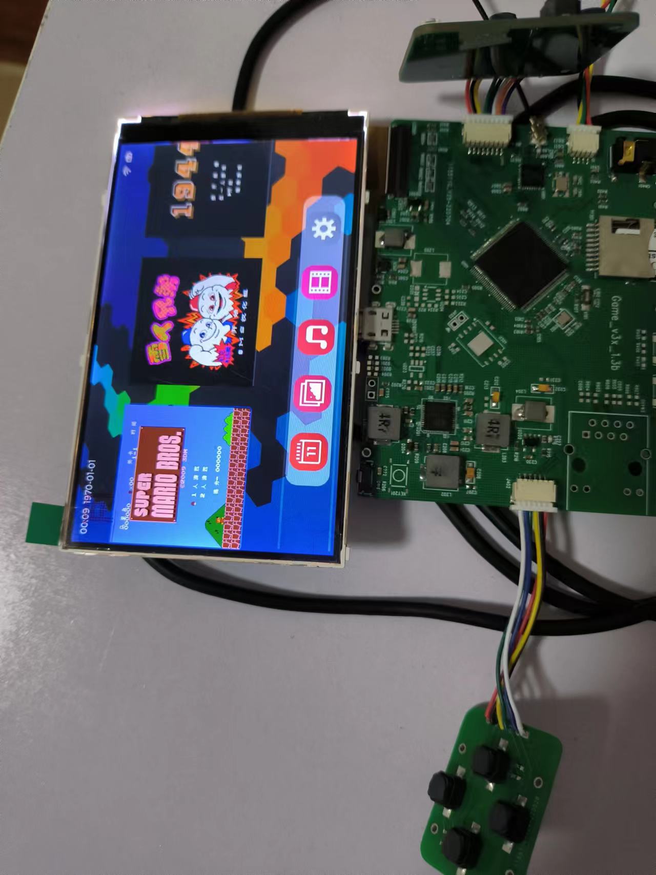
调试过程:https://whycan.com/t_7269.html
视屏展示 https://www.bilibili.com/video/BV1Bo4y1v7vf/?share_source=copy_web&vd_source=913316168904023e09eef6a4cdbb2f5c
设计文件,包含gerber,外壳,源码:https://github.com/qianniao29/game_v3x.git
软件还不完善,很多功能都没有做完,游戏可以玩,系统配置和升级等功能还没有实现,后面再慢慢填坑吧。。。
驱动上的问题,Linux系统关机有问题,lcd的背光调控无效
#4 Re: 全志 SOC » 用v3x做了个小板,分享一下 » 2023-02-03 21:16:45
请问一下参考了什么资料呢
主要参考了论坛上v3s的相关资料,编译uboot,kernel,驱动之类的。
#5 Re: 全志 SOC » 用v3x做了个小板,分享一下 » 2023-02-03 21:12:49
@qianniao29
请问uboot编译网口那,sun8i-v3x-game.dts这个文件在哪,我找了半天都没找到
完整的dts文件:
uboot sun8i-v3x-game.dts
// SPDX-License-Identifier: (GPL-2.0+ OR X11)
/*
* Copyright 2019 Icenowy Zheng <icenowy@aosc.io>
*/
/dts-v1/;
#include "sun8i-v3.dtsi"
#include <dt-bindings/gpio/gpio.h>
#include <dt-bindings/input/input.h>
/ {
model = "v3x handheld game console";
compatible = "v3x,v3x-game", "allwinner,sun8i-s3";
aliases {
serial0 = &uart0;
serial1 = &uart1;
serial2 = &uart2;
};
chosen {
stdout-path = "serial1:115200n8";
};
reg_vcc5v0: vcc5v0 {
compatible = "regulator-fixed";
regulator-name = "vcc5v0";
regulator-min-microvolt = <5000000>;
regulator-max-microvolt = <5000000>;
};
reg_vcc_wifi: vcc-wifi {
compatible = "regulator-fixed";
regulator-name = "vcc-wifi";
regulator-min-microvolt = <3300000>;
regulator-max-microvolt = <3300000>;
gpio = <&pio 1 2 GPIO_ACTIVE_LOW>; /* PB2 WIFI-EN */
vin-supply = <®_dcdc3>;
startup-delay-us = <200000>;
};
wifi_pwrseq: wifi_pwrseq {
compatible = "mmc-pwrseq-simple";
reset-gpios = <&pio 1 3 GPIO_ACTIVE_LOW>; /* PB3 WIFI-RST */
post-power-on-delay-ms = <200>;
};
};
&emac {
compatible = "allwinner,sun8i-h3-emac";
pinctrl-0 = <&emac_rgmii_pins>;
phy-handle = <&int_mii_phy>;
phy-mode = "mii";
allwinner,leds-active-high;
status = "okay";
};
&i2c0 {
status = "okay";
axp209: pmic@34 {
compatible = "x-powers,axp203",
"x-powers,axp209";
reg = <0x34>;
interrupt-parent = <&gic>;
interrupts = <GIC_SPI 32 IRQ_TYPE_LEVEL_HIGH>;
interrupt-controller;
#interrupt-cells = <1>;
};
};
&lradc {
vref-supply = <®_ldo2>;
status = "okay";
button-200 {
label = "Setup";
linux,code = <KEY_SETUP>;
channel = <0>;
voltage = <190000>;
};
};
&mmc0 {
vmmc-supply = <®_dcdc3>;
bus-width = <4>;
cd-gpios = <&pio 5 6 GPIO_ACTIVE_LOW>;
status = "okay";
};
&mmc1 {
vmmc-supply = <®_vcc_wifi>;
vqmmc-supply = <®_dcdc3>;
mmc-pwrseq = <&wifi_pwrseq>;
bus-width = <4>;
non-removable;
status = "okay";
};
&pio {
vcc-pd-supply = <®_dcdc3>;
vcc-pe-supply = <®_ldo3>;
uart1_pins: uart1-pins {
pins = "PG6", "PG7";
function = "uart1";
};
emac_rgmii_pins: emac0@0 {
allwinner,pins = "PD0", "PD1", "PD2", "PD3",
"PD4", "PD5", "PD7",
"PD8", "PD9", "PD10";
function = "emac";
drive-strength = <40>;
};
};
#include "axp209.dtsi"
&ac_power_supply {
status = "okay";
};
®_dcdc2 {
regulator-always-on;
regulator-min-microvolt = <1250000>;
regulator-max-microvolt = <1250000>;
regulator-name = "vdd-sys-cpu-ephy";
};
®_dcdc3 {
regulator-always-on;
regulator-min-microvolt = <3300000>;
regulator-max-microvolt = <3300000>;
regulator-name = "vcc-3v3";
};
®_ldo1 {
regulator-name = "vdd-rtc";
};
®_ldo2 {
regulator-always-on;
regulator-min-microvolt = <3000000>;
regulator-max-microvolt = <3000000>;
regulator-name = "avcc";
};
®_ldo3 {
regulator-min-microvolt = <2800000>;
regulator-max-microvolt = <2800000>;
regulator-name = "avdd-dovdd-2v8-csi";
regulator-soft-start;
regulator-ramp-delay = <1600>;
};
®_ldo4 {
regulator-min-microvolt = <1800000>;
regulator-max-microvolt = <1800000>;
regulator-name = "dvdd-1v8-csi";
};
&spi0 {
status = "okay";
flash@0 {
#address-cells = <1>;
#size-cells = <1>;
compatible = "winbond,w25q256", "jedec,spi-nor";
reg = <0>;
spi-max-frequency = <40000000>;
};
};
&uart1 {
pinctrl-0 = <&uart1_pins>;
pinctrl-names = "default";
status = "okay";
};
&usb_otg {
dr_mode = "host";
status = "okay";
};
&usbphy {
usb0_vbus-supply = <®_vcc5v0>;
status = "okay";
};kernel sun8i-v3x-game.dts
// SPDX-License-Identifier: (GPL-2.0+ OR X11)
/*
* Copyright 2019 Icenowy Zheng <icenowy@aosc.io>
*/
/dts-v1/;
#include "sun8i-v3.dtsi"
#include <dt-bindings/gpio/gpio.h>
#include <dt-bindings/input/input.h>
/ {
model = "v3x handheld game console";
compatible = "v3x,v3x-game", "sochip,s3", "allwinner,sun8i-v3";
aliases {
serial0 = &uart0;
serial1 = &uart1;
serial2 = &uart2;
spi0 = "/spi@1c68000";
spi1 = "/spi_gpio";
};
chosen {
stdout-path = "serial1:115200n8";
};
reg_vcc5v0: vcc5v0 {
compatible = "regulator-fixed";
regulator-name = "vcc5v0";
regulator-min-microvolt = <5000000>;
regulator-max-microvolt = <5000000>;
};
reg_vcc_wifi: vcc-wifi {
compatible = "regulator-fixed";
regulator-name = "vcc-wifi";
regulator-min-microvolt = <3300000>;
regulator-max-microvolt = <3300000>;
regulator-always-on;
gpio = <&pio 6 9 GPIO_ACTIVE_HIGH>; /* PG9 WIFI-EN */
enable-active-high;
vin-supply = <®_dcdc3>;
startup-delay-us = <200000>;
};
wifi_pwrseq: wifi_pwrseq {
compatible = "mmc-pwrseq-simple";
reset-gpios = <&pio 6 8 GPIO_ACTIVE_LOW>; /* PG8 WIFI-RST */
post-power-on-delay-ms = <200>;
};
reg_vcc_disp: vcc-lcd {
compatible = "regulator-fixed";
regulator-name = "display-power";
regulator-min-microvolt = <3300000>;
regulator-max-microvolt = <3300000>;
/* Collides with LCD E */
gpio = <&pio 3 20 GPIO_ACTIVE_LOW>; //PD20
enable-active-low;
};
dma: dma-controller@01c02000 {
compatible = "allwinner,sun8i-v3s-dma";
reg = <0x01c02000 0x1000>;
interrupts = <GIC_SPI 50 IRQ_TYPE_LEVEL_HIGH>;
clocks = <&ccu CLK_BUS_DMA>;
resets = <&ccu RST_BUS_DMA>;
#dma-cells = <1>;
};
ehci0: usb@01c1a000 {
compatible = "allwinner,sun8i-v3s-ehci", "generic-ehci";
reg = <0x01c1a000 0x100>;
interrupts = <GIC_SPI 72 IRQ_TYPE_LEVEL_HIGH>;
clocks = <&ccu CLK_BUS_EHCI0>, <&ccu CLK_BUS_OHCI0>;
resets = <&ccu RST_BUS_EHCI0>, <&ccu RST_BUS_OHCI0>;
status = "okay";
};
ohci0: usb@01c1a400 {
compatible = "allwinner,sun8i-v3s-ohci", "generic-ohci";
reg = <0x01c1a400 0x100>;
interrupts = <GIC_SPI 73 IRQ_TYPE_LEVEL_HIGH>;
clocks = <&ccu CLK_BUS_EHCI0>, <&ccu CLK_BUS_OHCI0>,
<&ccu CLK_USB_OHCI0>;
resets = <&ccu RST_BUS_EHCI0>, <&ccu RST_BUS_OHCI0>;
status = "okay";
};
pwm: pwm@1c21400 {
compatible = "allwinner,sun8i-v3s-pwm",
"allwinner,sun7i-a20-pwm";
reg = <0x01c21400 0x400>;
clocks = <&osc24M>;
#pwm-cells = <3>;
pinctrl-names = "default";
pinctrl-0 = <&pwm0_pins>;
status = "okay";
};
codec: codec@01c22c00 {
#sound-dai-cells = <0>;
compatible = "allwinner,sun8i-v3s-codec";
reg = <0x01c22c00 0x400>;
interrupts = <GIC_SPI 29 IRQ_TYPE_LEVEL_HIGH>;
clocks = <&ccu CLK_BUS_CODEC>, <&ccu CLK_AC_DIG>;
clock-names = "apb", "codec";
resets = <&ccu RST_BUS_CODEC>;
dmas = <&dma 15>, <&dma 15>;
dma-names = "rx", "tx";
allwinner,codec-analog-controls = <&codec_analog>;
allwinner,audio-routing =
"Headphone", "HP",
"Headphone", "HPCOM";
status = "okay";
};
codec_analog: codec-analog@01c23000 {
compatible = "allwinner,sun8i-v3s-codec-analog";
reg = <0x01c23000 0x4>;
};
backlight: backlight {
compatible = "pwm-backlight";
pwms = <&pwm 0 1000000 1>;
brightness-levels = <0 30 40 50 60 70 100>;
default-brightness-level = <6>;
};
spi_gpio {
compatible = "spi-gpio";
#address-cells = <1>;
#size-cells = <0>;
sck-gpios = <&pio 3 16 GPIO_ACTIVE_HIGH>; //PD16
miso-gpios = <&pio 3 19 GPIO_ACTIVE_HIGH>; //PD19
mosi-gpios = <&pio 3 21 GPIO_ACTIVE_HIGH>; //PD21
cs-gpios = <&pio 3 18 GPIO_ACTIVE_LOW>; //PD18
num-chipselects = <1>;
status = "okay";
panel: display@0 {
#address-cells = <1>;
#size-cells = <0>;
reg = <0>;
compatible = "easyquick,lm040", "simple-panel";
reset-gpios = <&pio 3 17 GPIO_ACTIVE_LOW>; //PD17
vcc-supply = <®_vcc_disp>;
iovcc-supply = <®_vcc_disp>;
pixel_swap_rb = <0x1>;
spi-max-frequency = <200000>;
port@0 {
reg = <0>;
backlight = <&backlight>;
#address-cells = <1>;
#size-cells = <0>;
panel_input: endpoint@0 {
reg = <0>;
remote-endpoint = <&tcon0_out_lcd>;
};
};
};
};
gpio_keys {
compatible = "gpio-keys-polled";
// pinctrl-names = "default";
// pinctrl-0 = <&key_pins>;
#address-cells = <1>;
#size-cells = <0>;
poll-interval = <20>;
button@0 {
label = "Key down";
linux,code = <KEY_DOWN>;
gpios = <&pio 2 6 GPIO_ACTIVE_LOW>; /* PC6 */
};
button@1 {
label = "Key right";
linux,code = <KEY_RIGHT>;
gpios = <&pio 2 7 GPIO_ACTIVE_LOW>; /* PC7 */
};
button@2 {
label = "Key left";
linux,code = <KEY_LEFT>;
gpios = <&pio 2 8 GPIO_ACTIVE_LOW>; /* PC8 */
};
button@3 {
label = "Key up";
linux,code = <KEY_UP>;
gpios = <&pio 2 9 GPIO_ACTIVE_LOW>; /* PC9 */
};
button@4 {
label = "Key b";
linux,code = <KEY_B>;
gpios = <&pio 3 12 GPIO_ACTIVE_LOW>; /* PD12 */
};
button@5 {
label = "Key a";
linux,code = <KEY_A>;
gpios = <&pio 3 13 GPIO_ACTIVE_LOW>; /* PD13 */
};
button@6 {
label = "Key enter";
linux,code = <KEY_ENTER>;
gpios = <&pio 3 14 GPIO_ACTIVE_LOW>; /* PD14 */
};
button@7 {
label = "Key menu";
linux,code = <KEY_MENU>;
gpios = <&pio 3 15 GPIO_ACTIVE_LOW>; /* PD15 */
};
button@8 {
label = "Key y";
linux,code = <KEY_Y>;
gpios = <&pio 4 21 GPIO_ACTIVE_LOW>; /* PE21 */
};
button@9 {
label = "Key x";
linux,code = <KEY_X>;
gpios = <&pio 4 22 GPIO_ACTIVE_LOW>; /* PE22 */
};
};
mbus: dram-controller@1c62000 {
compatible = "allwinner,sun8i-v3s-mbus";
reg = <0x01c62000 0x1000>,
<0x01c63000 0x1000>;
reg-names = "mbus", "dram";
clocks = <&ccu CLK_MBUS>,
<&ccu CLK_DRAM>,
<&ccu CLK_BUS_DRAM>;
clock-names = "mbus", "dram", "bus";
#address-cells = <1>;
#size-cells = <1>;
dma-ranges = <0x00000000 0x40000000 0x80000000>;
#interconnect-cells = <1>;
};
video-codec@1c0e000 {
compatible = "allwinner,sun8i-v3s-video-engine";
reg = <0x01c0e000 0x1000>;
clocks = <&ccu CLK_BUS_VE>, <&ccu CLK_VE>,
<&ccu CLK_DRAM_VE>;
clock-names = "ahb", "mod", "ram";
resets = <&ccu RST_BUS_VE>;
interrupts = <GIC_SPI 58 IRQ_TYPE_LEVEL_HIGH>;
allwinner,sram = <&ve_sram 1>;
};
};
&syscon {
sram_c: sram@4000 {
compatible = "mmio-sram";
reg = <0x4000 0xb000>;
#address-cells = <1>;
#size-cells = <1>;
ranges = <0 0x4000 0xb000>;
ve_sram: sram-section@0 {
compatible = "allwinner,sun8i-v3s-sram-c1",
"allwinner,sun4i-a10-sram-c1";
reg = <0x0 0xb000>;
};
};
};
&emac {
phy-handle = <&int_mii_phy>;
allwinner,leds-active-high;
phy-mode = "mii";
status = "okay";
};
&i2c0 {
status = "okay";
axp209: pmic@34 {
reg = <0x34>;
interrupt-parent = <&pio>;
interrupts = <1 5 IRQ_TYPE_EDGE_FALLING>; //PB5
};
};
&lradc {
vref-supply = <®_ldo2>;
status = "okay";
button-200 {
label = "Menu";
linux,code = <KEY_MENU>;
channel = <0>;
voltage = <191000>;
};
button-400 {
label = "Back";
linux,code = <KEY_BACK>;
channel = <0>;
voltage = <391000>;
};
button-600 {
label = "Vol Down";
linux,code = <KEY_VOLUMEDOWN>;
channel = <0>;
voltage = <600000>;
};
button-800 {
label = "Vol Up";
linux,code = <KEY_VOLUMEUP>;
channel = <0>;
voltage = <794000>;
};
};
&mmc0 {
vmmc-supply = <®_dcdc3>;
bus-width = <4>;
cd-gpios = <&pio 5 6 GPIO_ACTIVE_LOW>;
cap-sd-highspeed;
status = "okay";
};
&mmc1 {
vmmc-supply = <®_vcc_wifi>;
vqmmc-supply = <®_dcdc3>;
mmc-pwrseq = <&wifi_pwrseq>;
bus-width = <4>;
cap-sdio-irq;
non-removable;
status = "okay";
};
&pio {
uart1_pins: uart1-pins {
pins = "PG6", "PG7";
function = "uart1";
};
pwm0_pins: pwm0 {
pins = "PB4";
function = "pwm0";
};
lcd_rgb666_pins_a: lcd-rgb666-pe {
pins = "PE0", "PE1", "PE2", "PE3", "PE4", "PE5",
"PE6", "PE7", "PE8", "PE9", "PE10", "PE11",
"PE12", "PE13", "PE14", "PE15", "PE16", "PE17",
"PE18", "PE19", "PE23", "PE24";
function = "lcd";
};
key_pins: key_pins@0 {
pins = "PC6", "PC7", "PC8", "PC9",
"PD12", "PD13", "PD14", "PD15",
"PE21", "PE22";
function = "gpio_in";
allwinner,drive = <0>;
allwinner,pull = <1>;
};
};
#include "axp209.dtsi"
&axp209 {
battery_cell: battery-cell {
compatible = "simple-battery";
constant-charge-current-max-microamp = <1200000>;
};
};
&ac_power_supply {
status = "okay";
};
&battery_power_supply {
monitored-battery = <&battery_cell>;
status = "okay";
};
®_dcdc2 {
regulator-always-on;
regulator-min-microvolt = <1250000>;
regulator-max-microvolt = <1250000>;
regulator-name = "vdd-sys-cpu-ephy";
};
®_dcdc3 {
regulator-always-on;
regulator-min-microvolt = <3300000>;
regulator-max-microvolt = <3300000>;
regulator-name = "vcc-3v3";
};
®_ldo1 {
regulator-name = "vdd-rtc";
};
®_ldo2 {
regulator-always-on;
regulator-min-microvolt = <3000000>;
regulator-max-microvolt = <3000000>;
regulator-name = "avcc";
};
®_ldo3 {
regulator-min-microvolt = <2800000>;
regulator-max-microvolt = <2800000>;
regulator-name = "avdd-dovdd-2v8-csi";
regulator-soft-start;
regulator-ramp-delay = <1600>;
};
®_ldo4 {
regulator-min-microvolt = <1800000>;
regulator-max-microvolt = <3300000>;
regulator-name = "dvdd-1v8-csi";
};
&spi0 {
status = "okay";
flash@0 {
#address-cells = <1>;
#size-cells = <1>;
compatible = "winbond,w25q256", "jedec,spi-nor";
reg = <0>;
spi-max-frequency = <40000000>;
};
};
&uart1 {
pinctrl-0 = <&uart1_pins>;
pinctrl-names = "default";
status = "okay";
};
&usb_otg {
dr_mode = "host";
status = "okay";
};
&usbphy {
usb0_vbus-supply = <®_vcc5v0>;
status = "okay";
};
&de {
status = "okay";
};
&tcon0 {
pinctrl-names = "default";
pinctrl-0 = <&lcd_rgb666_pins_a>;
status = "okay";
};
&tcon0_out {
tcon0_out_lcd: endpoint@0 {
reg = <0>;
remote-endpoint = <&panel_input>;
};
};#6 Re: 全志 SOC » [v3x][kernel5.13.9]NT35510 LCD液晶屏(RGB+SPI接口)DRM驱动调试 » 2022-09-30 16:19:42
楼主uboot用的什么版本?
buildroot编译的uboot-2021.01
#7 Re: 全志 SOC » [v3x][kernel5.13.9]NT35510 LCD液晶屏(RGB+SPI接口)DRM驱动调试 » 2022-09-19 14:52:07
楼主,请问只有spi连接的lcd是显示数据也走spi吗?也能init成DRM_MODE_CONNECTOR_DPI吗?
应该不能吧,在tcon驱动部分还有部分drm对应的接口需要实现,只有spi的话,显示数据应该是用lcd的指令传输数据,也是走spi。spi屏可以用staging下的fbtft驱动。
#8 Re: 全志 SOC » 用v3x做了个小板,分享一下 » 2022-08-25 19:41:07
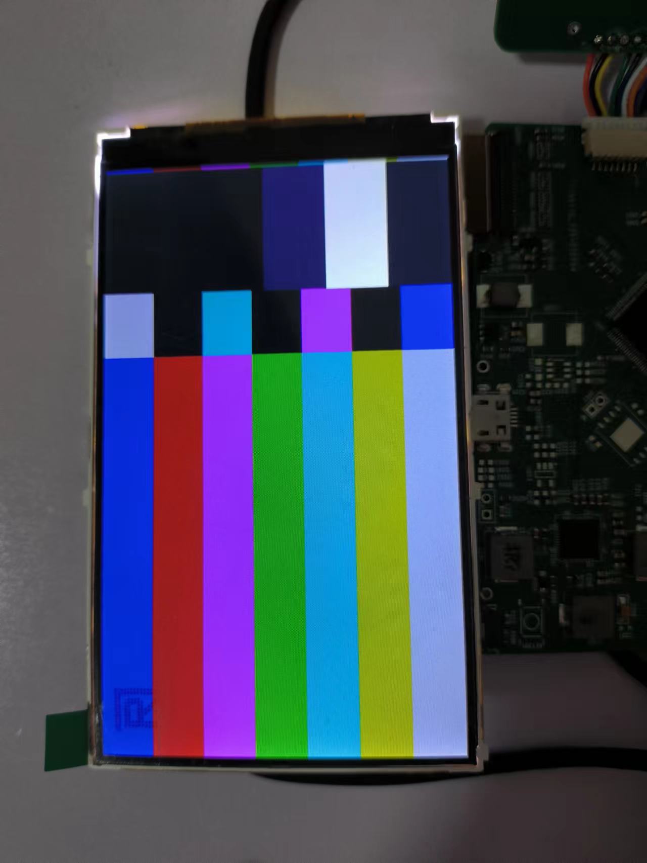
好久没来更新了,板子基本功能调试的差不多了,已初具雏形。屏幕调试花了挺长时间,调试记录见:https://whycan.com/t_8686.html
其他按键,esp8089,alsa音频参考论坛里的帖子调了调驱动。
#9 Re: 全志 SOC » [v3x][kernel5.13.9]NT35510 LCD液晶屏(RGB+SPI接口)DRM驱动调试 » 2022-08-25 19:20:17
RGB调试呢?期待楼主分享
RGB接口主要是上面贴的驱动文件中的时序调整,前肩和后肩的时间参考了屏幕卖家提供的示例程序,设置的比示例大一些然后慢慢减小,找到合适的值。参照datasheet中的时序配置前肩和后肩,无法正常点亮,所以这个得慢慢调整。硬件布线也需要注意减小干扰,不然也会出问题。
还有在probe的时候配置drm模式为rgb,drm_panel_init(&nt->panel, dev, &nt35510_drm_funcs, DRM_MODE_CONNECTOR_DPI);
TCON和mixer在v3s.dtsi中已经有了,使能即可。
.mode = {
		/* The internal pixel clock of the NT35510 is 20 MHz */
		.clock = 25000,
		.hdisplay = 480,
		.hsync_start = 480 + 2, /* HFP = 2 */
		.hsync_end = 480 + 2 + 1, /* HSync = 0 */
		.htotal = 480 + 2 + 1 + 5, /* HBP = 5 */
		.vdisplay = 800,
		.vsync_start = 800 + 24, /* VFP = 2 */
		.vsync_end = 800 + 24 + 1, /* VSync = 0 */
		.vtotal = 800 + 24 + 1 + 5, /* VBP = 5 */
		.flags = 0,
},#10 全志 SOC » [v3x][kernel5.13.9]NT35510 LCD液晶屏(RGB+SPI接口)DRM驱动调试 » 2022-08-24 21:48:07
- qianniao29
- 回复: 9
之前做了个v3x小板,lcd调了挺长时间,分享下调试过程。
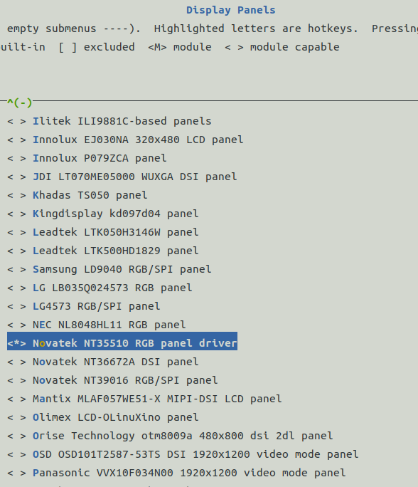
开启DRM,选择pannel中屏幕型号NT35510: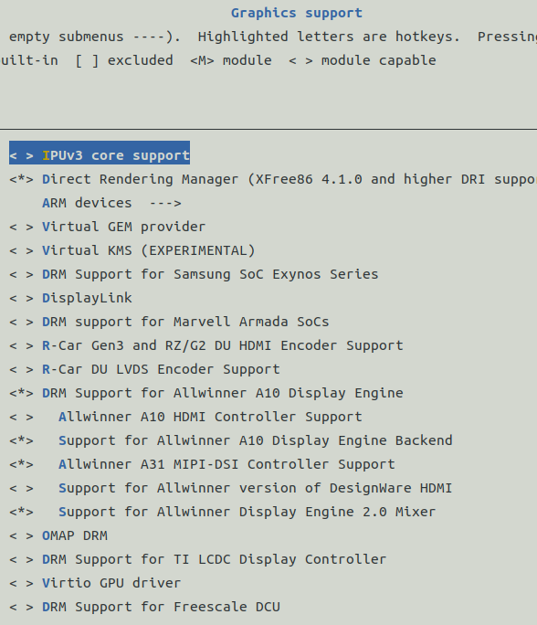
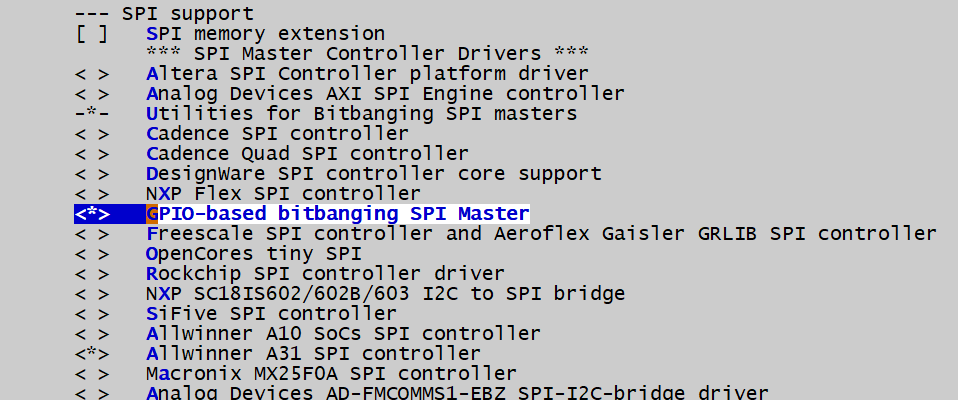
使用GPIO模拟spi,Linux有现成的驱动,开启即可。
在kernel 的menuconfig中选择driver/spi support/GPIO-based bitbanging SPI Master开启io模拟spi:
dts文件添加对应的节点:
spi_gpio {
        compatible = "spi-gpio";
        #address-cells = <0x1>;
        #size-cells = <0>;

        gpio-sck = <&pio 3 17 GPIO_ACTIVE_LOW>; //PD17
        gpio-miso = <&pio 3 15 GPIO_ACTIVE_LOW>; //PD15
        gpio-mosi = <&pio 3 14 GPIO_ACTIVE_LOW>; //PD14
        cs-gpios = <&pio 3 20 GPIO_ACTIVE_LOW>; //PD14
        num-chipselects = <1>;
        status = "okay";

        panel: display@0 {
            #address-cells = <1>;
            #size-cells = <0>;
            reg = <0>;
            compatible = "easyquick,lm040", "simple-panel";
            reset-gpios = <&pio 3 13 GPIO_ACTIVE_LOW>; //PD13
            pwren-gpios = <&pio 3 12 GPIO_ACTIVE_LOW>; //PD12
            spi-max-frequency = <2000000>;

            port@0 {
                reg = <0>;
                backlight = <&backlight>;
                #address-cells = <1>;
                #size-cells = <0>;

                panel_input: endpoint@0 {
                    reg = <0>;
                    remote-endpoint = <&tcon0_out_lcd>;
                };
            };
        };
    };
drivers/clk/sunxi-ng/ccu-sun8i-de2.c文件没有加入编译,需要修改drivers/clk/sunxi-ng/Makefile,添加
obj-$(CONFIG_DRM_SUN8I_MIXER) += ccu-sun8i-de2.o
模拟spi的时钟输出有bug,输出频率无法更改,需要修改spi-gpio.c中的延时函数:
diff --git a/drivers/spi/Kconfig b/drivers/spi/Kconfig
index 78f9fd0..0570dcd 100644
--- a/drivers/spi/Kconfig
+++ b/drivers/spi/Kconfig
@@ -143,6 +143,23 @@  config SPI_GPIO
       GPIO operations, you should be able to leverage that for better
       speed with a custom version of this driver; see the source code.

+config SLOWER_SPI_GPIO
+    bool "Enable delays in the GPIO-based bitbanging SPI Master"
+    default n
+    depends on SPI_GPIO
+    help
+      The GPIO bitbanging SPI master driver will run without any delays if this
+      option is not set. This option will enable the use of delays in the
+      operation of the GPIO bitbanging SPI master implementation to honour the
+      maximum speed of very slow devices.
+
+      To configure slow speed devices your board-specific setup logic must also
+      provide platform data assigning the speed for a device on a given chip
+      select of the GPIO bitbanging SPI master.
+
+      If your platform requires SPI buses driven at slow speeds select yes. If
+      in doubt, select no.
+
 config SPI_IMX_VER_IMX1
     def_bool y if SOC_IMX1

diff --git a/drivers/spi/spi_gpio.c b/drivers/spi/spi_gpio.c
index 63e51b0..b31fddd 100644
--- a/drivers/spi/spi_gpio.c
+++ b/drivers/spi/spi_gpio.c
@@ -19,6 +19,7 @@
  */
 #include <linux/kernel.h>
 #include <linux/init.h>
+#include <linux/delay.h>
 #include <linux/platform_device.h>
 #include <linux/gpio.h>

@@ -119,6 +120,9 @@  static inline int getmiso(const struct spi_device *spi)

 #undef pdata

+#if defined(CONFIG_SLOWER_SPI_GPIO)
+#define spidelay(nsecs) ndelay(nsecs)
+#else
 /*
  * NOTE:  this clocks "as fast as we can".  It "should" be a function of the
  * requested device clock.  Software overhead means we usually have trouble
@@ -126,6 +130,7 @@  static inline int getmiso(const struct spi_device *spi)
  * we'll just assume we never need additional per-bit slowdowns.
  */
 #define spidelay(nsecs)    do {} while (0)
+#endif

 #include "spi_bitbang_txrx.h"
参考NT35510 mipi接口的屏幕,修改为RGB接口驱动
drivers/gpu/drm/panel/panel-novatek-nt35510.c
// SPDX-License-Identifier: GPL-2.0-only
/*
 * Novatek NT35510 panel driver
 * Copyright (C) 2020 Linus Walleij <linus.walleij@linaro.org>
 * Based on code by Robert Teather (C) 2012 Samsung
 *
 * This display driver (and I refer to the physical component NT35510,
 * not this Linux kernel software driver) can handle:
 * 480x864, 480x854, 480x800, 480x720 and 480x640 pixel displays.
 * It has 480x840x24bit SRAM embedded for storing a frame.
 * When powered on the display is by default in 480x800 mode.
 *
 * The actual panels using this component have different names, but
 * the code needed to set up and configure the panel will be similar,
 * so they should all use the NT35510 driver with appropriate configuration
 * per-panel, e.g. for physical size.
 *
 * This driver is for the RGB (DPI) interface to panels using the NT35510.
 *
 */
#include <linux/backlight.h>
#include <linux/bitops.h>
#include <linux/gpio/consumer.h>
#include <linux/module.h>
#include <linux/of_device.h>
#include <linux/regmap.h>
#include <linux/regulator/consumer.h>

#include <linux/spi/spi.h>

#include <drm/drm_modes.h>
#include <drm/drm_panel.h>

#define MCS_CMD_MAUCCTR		0xF0 /* Manufacturer command enable */
#define MCS_CMD_READ_ID1	0xDA
#define MCS_CMD_READ_ID2	0xDB
#define MCS_CMD_READ_ID3	0xDC
#define MCS_CMD_MTP_READ_SETTING 0xF8 /* Uncertain about name */
#define MCS_CMD_MTP_READ_PARAM 0xFF /* Uncertain about name */
#define MCS_CMD_WRITE_BRIGHTNESS	0x51

/*
 * These manufacturer commands are available after we enable manufacturer
 * command set (MCS) for page 0.
 */
#define NT35510_P0_RGBCTR 0xB0
#define NT35510_P0_VIVIDCTR 0xB4
#define NT35510_P0_DOPCTR 0xB1
#define NT35510_P0_SDHDTCTR 0xB6
#define NT35510_P0_GSEQCTR 0xB7
#define NT35510_P0_SDEQCTR 0xB8
#define NT35510_P0_INVCTR 0xBC
#define NT35510_P0_DPFRCTR1 0xBD
#define NT35510_P0_DPFRCTR2 0xBE
#define NT35510_P0_DPFRCTR3 0xBF
#define NT35510_P0_DPMCTR12 0xCC

#define NT35510_P0_RGBCTR_LEN 5
#define NT35510_P0_DOPCTR_LEN 2
#define NT35510_P0_VIVIDCTR_LEN 1
#define NT35510_P0_GSEQCTR_LEN 2
#define NT35510_P0_SDEQCTR_LEN 4
#define NT35510_P0_SDVPCTR_LEN 1
#define NT35510_P0_DPFRCTR1_LEN 5
#define NT35510_P0_DPFRCTR2_LEN 5
#define NT35510_P0_DPFRCTR3_LEN 5
#define NT35510_P0_DPMCTR12_LEN 3

#define NT35510_DOPCTR_0_RAMKP BIT(7) /* Contents kept in sleep */
#define NT35510_DOPCTR_0_DSITE BIT(6) /* Enable TE signal */
#define NT35510_DOPCTR_0_DSIG BIT(5) /* Enable generic read/write */
#define NT35510_DOPCTR_0_DSIM BIT(4) /* Enable video mode on DSI */
#define NT35510_DOPCTR_0_EOTP BIT(3) /* Support EoTP */
#define NT35510_DOPCTR_0_N565 BIT(2) /* RGB or BGR pixel format */
#define NT35510_DOPCTR_1_TW_PWR_SEL BIT(4) /* TE power selector */
#define NT35510_DOPCTR_1_CRGB BIT(3) /* RGB or BGR byte order */
#define NT35510_DOPCTR_1_CTB BIT(2) /* Vertical scanning direction */
#define NT35510_DOPCTR_1_CRL BIT(1) /* Source driver data shift */
#define NT35510_P0_SDVPCTR_PRG BIT(2) /* 0 = normal operation, 1 = VGLO */
#define NT35510_P0_SDVPCTR_AVDD 0 /* source driver output = AVDD */
#define NT35510_P0_SDVPCTR_OFFCOL 1 /* source driver output = off color */
#define NT35510_P0_SDVPCTR_AVSS 2 /* source driver output = AVSS */
#define NT35510_P0_SDVPCTR_HI_Z 3 /* source driver output = High impedance */

/*
 * These manufacturer commands are available after we enable manufacturer
 * command set (MCS) for page 1.
 */
#define NT35510_P1_SETAVDD 0xB0
#define NT35510_P1_SETAVEE 0xB1
#define NT35510_P1_SETVCL 0xB2
#define NT35510_P1_SETVGH 0xB3
#define NT35510_P1_SETVRGH 0xB4
#define NT35510_P1_SETVGL 0xB5
#define NT35510_P1_BT1CTR 0xB6
#define NT35510_P1_BT2CTR 0xB7
#define NT35510_P1_BT3CTR 0xB8
#define NT35510_P1_BT4CTR 0xB9 /* VGH boosting times/freq */
#define NT35510_P1_BT5CTR 0xBA
#define NT35510_P1_PFMCTR 0xBB
#define NT35510_P1_SETVGP 0xBC
#define NT35510_P1_SETVGN 0xBD
#define NT35510_P1_SETVCMOFF 0xBE
#define NT35510_P1_VGHCTR 0xBF /* VGH output ctrl */
#define NT35510_P1_SET_GAMMA_RED_POS 0xD1
#define NT35510_P1_SET_GAMMA_GREEN_POS 0xD2
#define NT35510_P1_SET_GAMMA_BLUE_POS 0xD3
#define NT35510_P1_SET_GAMMA_RED_NEG 0xD4
#define NT35510_P1_SET_GAMMA_GREEN_NEG 0xD5
#define NT35510_P1_SET_GAMMA_BLUE_NEG 0xD6

/* AVDD and AVEE setting 3 bytes */
#define NT35510_P1_AVDD_LEN 3
#define NT35510_P1_AVEE_LEN 3
#define NT35510_P1_VGH_LEN 3
#define NT35510_P1_VGL_LEN 3
#define NT35510_P1_VGP_LEN 3
#define NT35510_P1_VGN_LEN 3
/* BT1CTR thru BT5CTR setting 3 bytes */
#define NT35510_P1_BT1CTR_LEN 3
#define NT35510_P1_BT2CTR_LEN 3
#define NT35510_P1_BT4CTR_LEN 3
#define NT35510_P1_BT5CTR_LEN 3
/* 52 gamma parameters times two per color: positive and negative */
#define NT35510_P1_GAMMA_LEN 52

/**
 * struct nt35510_config - the display-specific NT35510 configuration
 *
 * Some of the settings provide an array of bytes, A, B C which mean:
 * A = normal / idle off mode
 * B = idle on mode
 * C = partial / idle off mode
 *
 * Gamma correction arrays are 10bit numbers, two consecutive bytes
 * makes out one point on the gamma correction curve. The points are
 * not linearly placed along the X axis, we get points 0, 1, 3, 5
 * 7, 11, 15, 23, 31, 47, 63, 95, 127, 128, 160, 192, 208, 224, 232,
 * 240, 244, 248, 250, 252, 254, 255. The voltages tuples form
 * V0, V1, V3 ... V255, with 0x0000 being the lowest voltage and
 * 0x03FF being the highest voltage.
 *
 * Each value must be strictly higher than the previous value forming
 * a rising curve like this:
 *
 * ^
 * |                                        V255
 * |                                 V254
 * |                         ....
 * |                    V5
 * |           V3
 * |     V1
 * | V0
 * +------------------------------------------->
 *
 * The details about all settings can be found in the NT35510 Application
 * Note.
 */
struct nt35510_config {
	/**
	 * @width_mm: physical panel width [mm]
	 */
	u32 width_mm;
	/**
	 * @height_mm: physical panel height [mm]
	 */
	u32 height_mm;
	/**
	 * @mode: the display mode. This is only relevant outside the panel
	 * in video mode: in command mode this is configuring the internal
	 * timing in the display controller.
	 */
	const struct drm_display_mode mode;
	/**
	 * @avdd: setting for AVDD ranging from 0x00 = 6.5V to 0x14 = 4.5V
	 * in 0.1V steps the default is 0x05 which means 6.0V
	 */
	u8 avdd[NT35510_P1_AVDD_LEN];
	/**
	 * @bt1ctr: setting for boost power control for the AVDD step-up
	 * circuit (1)
	 * bits 0..2 in the lower nibble controls PCK, the booster clock
	 * frequency for the step-up circuit:
	 * 0 = Hsync/32
	 * 1 = Hsync/16
	 * 2 = Hsync/8
	 * 3 = Hsync/4
	 * 4 = Hsync/2
	 * 5 = Hsync
	 * 6 = Hsync x 2
	 * 7 = Hsync x 4
	 * bits 4..6 in the upper nibble controls BTP, the boosting
	 * amplification for the the step-up circuit:
	 * 0 = Disable
	 * 1 = 1.5 x VDDB
	 * 2 = 1.66 x VDDB
	 * 3 = 2 x VDDB
	 * 4 = 2.5 x VDDB
	 * 5 = 3 x VDDB
	 * The defaults are 4 and 4 yielding 0x44
	 */
	u8 bt1ctr[NT35510_P1_BT1CTR_LEN];
	/**
	 * @avee: setting for AVEE ranging from 0x00 = -6.5V to 0x14 = -4.5V
	 * in 0.1V steps the default is 0x05 which means -6.0V
	 */
	u8 avee[NT35510_P1_AVEE_LEN];
	/**
	 * @bt2ctr: setting for boost power control for the AVEE step-up
	 * circuit (2)
	 * bits 0..2 in the lower nibble controls NCK, the booster clock
	 * frequency, the values are the same as for PCK in @bt1ctr.
	 * bits 4..5 in the upper nibble controls BTN, the boosting
	 * amplification for the the step-up circuit.
	 * 0 = Disable
	 * 1 = -1.5 x VDDB
	 * 2 = -2 x VDDB
	 * 3 = -2.5 x VDDB
	 * 4 = -3 x VDDB
	 * The defaults are 4 and 3 yielding 0x34
	 */
	u8 bt2ctr[NT35510_P1_BT2CTR_LEN];
	/**
	 * @vgh: setting for VGH ranging from 0x00 = 7.0V to 0x0B = 18.0V
	 * in 1V steps, the default is 0x08 which means 15V
	 */
	u8 vgh[NT35510_P1_VGH_LEN];
	/**
	 * @bt4ctr: setting for boost power control for the VGH step-up
	 * circuit (4)
	 * bits 0..2 in the lower nibble controls HCK, the booster clock
	 * frequency, the values are the same as for PCK in @bt1ctr.
	 * bits 4..5 in the upper nibble controls BTH, the boosting
	 * amplification for the the step-up circuit.
	 * 0 = AVDD + VDDB
	 * 1 = AVDD - AVEE
	 * 2 = AVDD - AVEE + VDDB
	 * 3 = AVDD x 2 - AVEE
	 * The defaults are 4 and 3 yielding 0x34
	 */
	u8 bt4ctr[NT35510_P1_BT4CTR_LEN];
	/**
	 * @vgl: setting for VGL ranging from 0x00 = -2V to 0x0f = -15V in
	 * 1V steps, the default is 0x08 which means -10V
	 */
	u8 vgl[NT35510_P1_VGL_LEN];
	/**
	 * @bt5ctr: setting for boost power control for the VGL step-up
	 * circuit (5)
	 * bits 0..2 in the lower nibble controls LCK, the booster clock
	 * frequency, the values are the same as for PCK in @bt1ctr.
	 * bits 4..5 in the upper nibble controls BTL, the boosting
	 * amplification for the the step-up circuit.
	 * 0 = AVEE + VCL
	 * 1 = AVEE - AVDD
	 * 2 = AVEE + VCL - AVDD
	 * 3 = AVEE x 2 - AVDD
	 * The defaults are 3 and 2 yielding 0x32
	 */
	u8 bt5ctr[NT35510_P1_BT5CTR_LEN];
	/**
	 * @vgp: setting for VGP, the positive gamma divider voltages
	 * VGMP the high voltage and VGSP the low voltage.
	 * The first byte contains bit 8 of VGMP and VGSP in bits 4 and 0
	 * The second byte contains bit 0..7 of VGMP
	 * The third byte contains bit 0..7 of VGSP
	 * VGMP 0x00 = 3.0V .. 0x108 = 6.3V in steps of 12.5mV
	 * VGSP 0x00 = 0V .. 0x111 = 3.7V in steps of 12.5mV
	 */
	u8 vgp[NT35510_P1_VGP_LEN];
	/**
	 * @vgn: setting for VGN, the negative gamma divider voltages,
	 * same layout of bytes as @vgp.
	 */
	u8 vgn[NT35510_P1_VGN_LEN];
	/**
	 * @sdeqctr: Source driver control settings, first byte is
	 * 0 for mode 1 and 1 for mode 2. Mode 1 uses two steps and
	 * mode 2 uses three steps meaning EQS3 is not used in mode
	 * 1. Mode 2 is default. The last three parameters are EQS1, EQS2
	 * and EQS3, setting the rise time for each equalizer step:
	 * 0x00 = 0.0 us to 0x0f = 7.5 us in steps of 0.5us. The default
	 * is 0x07 = 3.5 us.
	 */
	u8 sdeqctr[NT35510_P0_SDEQCTR_LEN];
	/**
	 * @sdvpctr: power/voltage behaviour during vertical porch time
	 */
	u8 sdvpctr;
	/**
	 * @rgb_mode: the operation status and vertical / horizontal porch
	 * of RGB interface. The setting becomes effective as soon as the
	 * command is received.
	 */
	u8 rgb_mode;
	/**
	 * @psel: pixel clock divisor: 0 = 1, 1 = 2, 2 = 4, 3 = 8.
	 */
	u8 psel;
	/**
	 * @dpmctr12: Display timing control 12
	 * Byte 1 bit 4 selects LVGL voltage level: 0 = VGLX, 1 = VGL_REG
	 * Byte 1 bit 1 selects gate signal mode: 0 = non-overlap, 1 = overlap
	 * Byte 1 bit 0 selects output signal control R/L swap, 0 = normal
	 * 1 = swap all O->E, L->R
	 * Byte 2 is CLW delay clock for CK O/E and CKB O/E signals:
	 * 0x00 = 0us .. 0xFF = 12.75us in 0.05us steps
	 * Byte 3 is FTI_H0 delay time for STP O/E signals:
	 * 0x00 = 0us .. 0xFF = 12.75us in 0.05us steps
	 */
	u8 dpmctr12[NT35510_P0_DPMCTR12_LEN];
	/**
	 * @gamma_corr_pos_r: Red gamma correction parameters, positive
	 */
	u8 gamma_corr_pos_r[NT35510_P1_GAMMA_LEN];
	/**
	 * @gamma_corr_pos_g: Green gamma correction parameters, positive
	 */
	u8 gamma_corr_pos_g[NT35510_P1_GAMMA_LEN];
	/**
	 * @gamma_corr_pos_b: Blue gamma correction parameters, positive
	 */
	u8 gamma_corr_pos_b[NT35510_P1_GAMMA_LEN];
	/**
	 * @gamma_corr_neg_r: Red gamma correction parameters, negative
	 */
	u8 gamma_corr_neg_r[NT35510_P1_GAMMA_LEN];
	/**
	 * @gamma_corr_neg_g: Green gamma correction parameters, negative
	 */
	u8 gamma_corr_neg_g[NT35510_P1_GAMMA_LEN];
	/**
	 * @gamma_corr_neg_b: Blue gamma correction parameters, negative
	 */
	u8 gamma_corr_neg_b[NT35510_P1_GAMMA_LEN];
};

/**
 * struct nt35510 - state container for the NT35510 panel
 */
struct nt35510 {
	/**
	 * @dev: the container device
	 */
	struct device *dev;
	/**
	 * @conf: the specific panel configuration, as the NT35510
	 * can be combined with many physical panels, they can have
	 * different physical dimensions and gamma correction etc,
	 * so this is stored in the config.
	 */
	const struct nt35510_config *conf;
	/**
	 * @panel: the DRM panel object for the instance
	 */
	struct drm_panel panel;
	/**
	 * @regmap: the regmap for the SPI
	 */
	struct regmap *regmap;
	/**
	 * @supplies: regulators supplying the panel
	 */
	struct regulator_bulk_data supplies[2];
	/**
	 * @reset_gpio: the reset line
	 */
	struct gpio_desc *reset_gpio;
	 /**
	 * @pwren_gpio: the power enable line
	 */
	struct gpio_desc *pwren_gpio;

	u32 swap_rb;
};

/* Manufacturer command has strictly this byte sequence */
static const u8 nt35510_mauc_mtp_read_param[] = { 0xAA, 0x55, 0x25, 0x01 };
static const u8 nt35510_mauc_mtp_read_setting[] = { 0x01, 0x02, 0x00, 0x20,
						    0x33, 0x13, 0x00, 0x40,
						    0x00, 0x00, 0x23, 0x02 };
static const u8 nt35510_mauc_select_page_0[] = { 0x55, 0xAA, 0x52, 0x08, 0x00 };
static const u8 nt35510_mauc_select_page_1[] = { 0x55, 0xAA, 0x52, 0x08, 0x01 };
static const u8 nt35510_vgh_on[] = { 0x01 };

static inline struct nt35510 *panel_to_nt35510(struct drm_panel *panel)
{
	return container_of(panel, struct nt35510, panel);
}


#define NT35510_ROTATE_0_SETTING	0x02
#define NT35510_ROTATE_180_SETTING	0x00

static int nt35510_send(struct nt35510 *nt, u8 cmd, u8 len, const u8 *seq)
{
	struct spi_device *spi = to_spi_device(nt->dev);
	int	ret = 0;
	u8	buffer[2];
	u8	index = 0;

	if(len == 0)
	{
		buffer[0] = 0x20;	//cmd high byte
		buffer[1] = cmd;
		if((ret = spi_write_then_read(spi, buffer, 2, NULL, 0)) !=0)
			return ret;
		buffer[0] = 0x00;	//cmd low byte
		buffer[1] = 0x00;
		if((ret = spi_write_then_read(spi, buffer, 2, NULL, 0)) !=0)
			return ret;

	}
	while (index < len)
	{
		buffer[0] = 0x20;	//cmd high byte
		buffer[1] = cmd;
		if((ret = spi_write_then_read(spi, buffer, 2, NULL, 0)) !=0)
			break;
		buffer[0] = 0x00;	//cmd low byte
		buffer[1] = index;
		if((ret = spi_write_then_read(spi, buffer, 2, NULL, 0)) !=0)
			break;
		buffer[0] = 0x40;	//data low byte
		buffer[1] = seq[index];
		if((ret = spi_write_then_read(spi, buffer, 2, NULL, 0)) !=0)
			break;
		index++;
	}

	return ret;
}

static int nt35510_read(struct nt35510 *nt, u8 cmd, u8 len, const u8 *seq)
{
	struct spi_device *spi = to_spi_device(nt->dev);
	u8	buffer[2];
	u8	index = 0;
	int	ret = 0;

	while (index < len)
	{
		buffer[0] = 0x20;	//cmd high byte
		buffer[1] = cmd;
		if((ret = spi_write_then_read(spi, buffer, 2, NULL, 0)) !=0)
			break;

		buffer[0] = 0x00;	//cmd low byte
		buffer[1] = index;
		if((ret = spi_write_then_read(spi, buffer, 2, NULL, 0)) !=0)
			break;

		buffer[0] = 0xC0;	//data low byte
		if((ret = spi_write_then_read(spi, buffer, 1, (void*)&seq[index], 1)) !=0)
			break;
		index++;
	}

	return ret;
}


static int nt35510_read_id(struct nt35510 *nt)
{
	u8 id1, id2, id3;
	int ret;

	ret = nt35510_read(nt, MCS_CMD_READ_ID1, 1, &id1);
	if (ret < 0) {
		dev_err(nt->dev, "could not read MTP ID1\n");
		return ret;
	}
	ret = nt35510_read(nt, MCS_CMD_READ_ID2, 1, &id2);
	if (ret < 0) {
		dev_err(nt->dev, "could not read MTP ID2\n");
		return ret;
	}
	ret = nt35510_read(nt, MCS_CMD_READ_ID3, 1, &id3);
	if (ret < 0) {
		dev_err(nt->dev, "could not read MTP ID3\n");
		return ret;
	}

	/*
	 * Multi-Time Programmable (?) memory contains manufacturer
	 * ID (e.g. Hydis 0x55), driver ID (e.g. NT35510 0xc0) and
	 * version.
	 */
	dev_info(nt->dev, "MTP ID manufacturer: %02x version: %02x driver: %02x\n", id1, id2, id3);
	ret = nt35510_read(nt, 0x0c, 1, &id1);
	dev_info(nt->dev, "Pixel Format:0x%x\n", id1);

	return 0;
}

/**
 * nt35510_setup_power() - set up power config in page 1
 * @nt: the display instance to set up
 */
static int nt35510_setup_power(struct nt35510 *nt)
{
	int ret;

	ret = nt35510_send(nt,  NT35510_P1_SETAVDD,
				NT35510_P1_AVDD_LEN,
				nt->conf->avdd);
	if (ret)
		return ret;
	ret = nt35510_send(nt,  NT35510_P1_BT1CTR,
				NT35510_P1_BT1CTR_LEN,
				nt->conf->bt1ctr);
	if (ret)
		return ret;
	ret = nt35510_send(nt,  NT35510_P1_SETAVEE,
				NT35510_P1_AVEE_LEN,
				nt->conf->avee);
	if (ret)
		return ret;
	ret = nt35510_send(nt,  NT35510_P1_BT2CTR,
				NT35510_P1_BT2CTR_LEN,
				nt->conf->bt2ctr);
	if (ret)
		return ret;
	ret = nt35510_send(nt,  NT35510_P1_SETVGH,
				NT35510_P1_VGH_LEN,
				nt->conf->vgh);
	if (ret)
		return ret;
	ret = nt35510_send(nt,  NT35510_P1_BT4CTR,
				NT35510_P1_BT4CTR_LEN,
				nt->conf->bt4ctr);
	if (ret)
		return ret;
	ret = nt35510_send(nt,  NT35510_P1_VGHCTR,
				ARRAY_SIZE(nt35510_vgh_on),
				nt35510_vgh_on);
	if (ret)
		return ret;
	ret = nt35510_send(nt,  NT35510_P1_SETVGL,
				NT35510_P1_VGL_LEN,
				nt->conf->vgl);
	if (ret)
		return ret;
	ret = nt35510_send(nt,  NT35510_P1_BT5CTR,
				NT35510_P1_BT5CTR_LEN,
				nt->conf->bt5ctr);
	if (ret)
		return ret;
	ret = nt35510_send(nt,  NT35510_P1_SETVGP,
				NT35510_P1_VGP_LEN,
				nt->conf->vgp);
	if (ret)
		return ret;
	ret = nt35510_send(nt,  NT35510_P1_SETVGN,
				NT35510_P1_VGN_LEN,
				nt->conf->vgn);
	if (ret)
		return ret;

	/* Typically 10 ms */
	usleep_range(10000, 20000);

	return 0;
}

/**
 * nt35510_setup_display() - set up display config in page 0
 * @nt: the display instance to set up
 */
static int nt35510_setup_display(struct nt35510 *nt)
{
	const struct nt35510_config *conf = nt->conf;
	u8 dopctr[NT35510_P0_DOPCTR_LEN];
	u8 gseqctr[NT35510_P0_GSEQCTR_LEN];
	u8 dpfrctr[NT35510_P0_DPFRCTR1_LEN];
	/* FIXME: set up any rotation (assume none for now) */
	u8 val;
	int ret;

	/* Enable TE, EoTP and RGB pixel format */
	dopctr[0] = 0x10;
	ret = nt35510_send(nt,  NT35510_P0_VIVIDCTR,
				NT35510_P0_VIVIDCTR_LEN,
				dopctr);
	if (ret)
		return ret;

/*	ret = mipi_dsi_dcs_write(dsi, MIPI_DCS_SET_ADDRESS_MODE, &addr_mode,
				 sizeof(addr_mode));
	if (ret < 0)
		return ret;*/

	/*
	 * Source data hold time, default 0x05 = 2.5us
	 * 0x00..0x3F = 0 .. 31.5us in steps of 0.5us
	 * 0x0A = 5us
	 */
	val = 0x0A;
	ret = nt35510_send(nt, NT35510_P0_SDHDTCTR, sizeof(val),
				&val);
	if (ret < 0)
		return ret;

	/* EQ control for gate signals, 0x00 = 0 us */
	gseqctr[0] = 0x00;
	gseqctr[1] = 0x00;
	ret = nt35510_send(nt,  NT35510_P0_GSEQCTR,
				NT35510_P0_GSEQCTR_LEN,
				gseqctr);
	if (ret)
		return ret;

	ret = nt35510_send(nt,  NT35510_P0_SDEQCTR,
				NT35510_P0_SDEQCTR_LEN,
				conf->sdeqctr);
	if (ret)
		return ret;

	dpfrctr[0] = 0x05;
	dpfrctr[1] = 0x05;
	dpfrctr[2] = 0x05;
	ret = nt35510_send(nt, NT35510_P0_INVCTR,
				3, dpfrctr);
	if (ret < 0)
		return ret;

	/*
	 * Display timing control for active and idle off mode:
	 * the first byte contains
	 * the two high bits of T1A and second byte the low 8 bits, and
	 * the valid range is 0x100 (257) to 0x3ff (1023) representing
	 * 258..1024 (+1) pixel clock ticks for one scanline. At 20MHz pixel
	 * clock this covers the range of 12.90us .. 51.20us in steps of
	 * 0.05us, the default is 0x184 (388) representing 389 ticks.
	 * The third byte is VBPDA, vertical back porch display active
	 * and the fourth VFPDA, vertical front porch display active,
	 * both given in number of scanlines in the range 0x02..0xff
	 * for 2..255 scanlines. The fifth byte is 2 bits selecting
	 * PSEL for active and idle off mode, how much the 20MHz clock
	 * is divided by 0..3.  This needs to be adjusted to get the right
	 * frame rate.
	 */
	dpfrctr[0] = conf->rgb_mode;
	/* V-Sync back porch */
	dpfrctr[1] = conf->mode.vtotal - conf->mode.vsync_start;
	/* V-Sync front porch */
	dpfrctr[2] = conf->mode.vsync_start - conf->mode.vdisplay;
	/* V-Sync back porch */
	dpfrctr[3] = conf->mode.htotal - conf->mode.hsync_start;
	/* front porch */
	dpfrctr[4] = conf->mode.hsync_start - conf->mode.hdisplay;
	ret = nt35510_send(nt,  NT35510_P0_RGBCTR,
				NT35510_P0_RGBCTR_LEN,
				dpfrctr);
	if (ret)
		return ret;

	if(nt->swap_rb)
	{
		dopctr[0] = 0x08; //swap R and B
		ret = nt35510_send(nt, 0x36, 1, dopctr);
		dopctr[0] = 0x0;
		ret = nt35510_read(nt, 0x0b, 1, dopctr);
			dev_info(nt->dev, "RGB Format:0x%x\n", dopctr[0]);
	}

	ret = nt35510_send(nt, 0x11, 0, NULL); //sleep out & booster on
	usleep_range(120000, 140000);
	ret = nt35510_send(nt, 0x29, 0, NULL); //Display On
	usleep_range(120000, 140000);
#if 0
//	ret = nt35510_send(nt, 0x23, 1, dopctr); //All pixel on
	dpfrctr[0] = 0;
	dpfrctr[1] = 0;
	dpfrctr[2] = 0x01;
	dpfrctr[3] = 0x90;
	ret = nt35510_send(nt, 0x2a, 4, dpfrctr);
	ret = nt35510_send(nt, 0x2b, 4, dpfrctr);
	ret = nt35510_send(nt, 0x2c, 0, NULL);

	dopctr[0] = 0;
	ret = nt35510_send(nt, 0x4a, 1, dpfrctr);
#endif

	return 0;
}

static int nt35510_set_brightness(struct backlight_device *bl)
{
	struct nt35510 *nt = bl_get_data(bl);
	u8 brightness = bl->props.brightness;
	int ret;

	dev_dbg(nt->dev, "set brightness %d\n", brightness);
	ret = nt35510_send(nt, MCS_CMD_WRITE_BRIGHTNESS,
				1, &brightness);
	if (ret < 0)
		return ret;

	return 0;
}

static const struct backlight_ops nt35510_bl_ops = {
	.update_status = nt35510_set_brightness,
};

/*
 * This power-on sequence
 */
static int nt35510_power_on(struct nt35510 *nt)
{
	int ret;

	ret = regulator_bulk_enable(ARRAY_SIZE(nt->supplies), nt->supplies);
	if (ret < 0) {
		dev_err(nt->dev, "unable to enable regulators\n");
		return ret;
	}

	/* Toggle RESET in accordance with datasheet page 370 */
	if (nt->reset_gpio) {
		gpiod_set_value(nt->reset_gpio, 1);
		/* Active min 10 us according to datasheet, let's say 20 */
		usleep_range(120000, 140000);
		gpiod_set_value(nt->reset_gpio, 0);
		/*
		 * 5 ms during sleep mode, 120 ms during sleep out mode
		 * according to datasheet, let's use 120-140 ms.
		 */
		usleep_range(120000, 140000);
	}

	ret = nt35510_send(nt,  MCS_CMD_MTP_READ_PARAM,
				ARRAY_SIZE(nt35510_mauc_mtp_read_param),
				nt35510_mauc_mtp_read_param);
	if (ret)
		return ret;

	ret = nt35510_send(nt,  MCS_CMD_MTP_READ_SETTING,
				ARRAY_SIZE(nt35510_mauc_mtp_read_setting),
				nt35510_mauc_mtp_read_setting);
	if (ret)
		return ret;

	nt35510_read_id(nt);

	/* Set up stuff in  manufacturer control, page 1 */
	ret = nt35510_send(nt,  MCS_CMD_MAUCCTR,
				ARRAY_SIZE(nt35510_mauc_select_page_1),
				nt35510_mauc_select_page_1);
	if (ret)
		return ret;

	ret = nt35510_setup_power(nt);
	if (ret)
		return ret;

	ret = nt35510_send(nt,  NT35510_P1_SET_GAMMA_RED_POS,
				NT35510_P1_GAMMA_LEN,
				nt->conf->gamma_corr_pos_r);
	if (ret)
		return ret;
	ret = nt35510_send(nt,  NT35510_P1_SET_GAMMA_GREEN_POS,
				NT35510_P1_GAMMA_LEN,
				nt->conf->gamma_corr_pos_g);
	if (ret)
		return ret;
	ret = nt35510_send(nt,  NT35510_P1_SET_GAMMA_BLUE_POS,
				NT35510_P1_GAMMA_LEN,
				nt->conf->gamma_corr_pos_b);
	if (ret)
		return ret;
	ret = nt35510_send(nt,  NT35510_P1_SET_GAMMA_RED_NEG,
				NT35510_P1_GAMMA_LEN,
				nt->conf->gamma_corr_neg_r);
	if (ret)
		return ret;
	ret = nt35510_send(nt,  NT35510_P1_SET_GAMMA_GREEN_NEG,
				NT35510_P1_GAMMA_LEN,
				nt->conf->gamma_corr_neg_g);
	if (ret)
		return ret;
	ret = nt35510_send(nt,  NT35510_P1_SET_GAMMA_BLUE_NEG,
				NT35510_P1_GAMMA_LEN,
				nt->conf->gamma_corr_neg_b);
	if (ret)
		return ret;

	/* Set up stuff in  manufacturer control, page 0 */
	ret = nt35510_send(nt,  MCS_CMD_MAUCCTR,
				ARRAY_SIZE(nt35510_mauc_select_page_0),
				nt35510_mauc_select_page_0);
	if (ret)
		return ret;

	ret = nt35510_setup_display(nt);
	if (ret)
		return ret;

	return 0;
}

static int nt35510_power_off(struct nt35510 *nt)
{
	int ret;

	ret = regulator_bulk_disable(ARRAY_SIZE(nt->supplies), nt->supplies);
	if (ret)
		return ret;

	if (nt->reset_gpio)
		gpiod_set_value(nt->reset_gpio, 1);

	return 0;
}

static int nt35510_unprepare(struct drm_panel *panel)
{
	struct nt35510 *nt = panel_to_nt35510(panel);
	int ret;

	ret = nt35510_power_off(nt);
	if (ret)
		return ret;

	return 0;
}

static int nt35510_prepare(struct drm_panel *panel)
{
	struct nt35510 *nt = panel_to_nt35510(panel);
	int ret;

	ret = nt35510_power_on(nt);
	if (ret)
		return ret;

	return 0;
}

static int nt35510_get_modes(struct drm_panel *panel,
			     struct drm_connector *connector)
{
	struct nt35510 *nt = panel_to_nt35510(panel);
	struct drm_display_mode *mode;
	struct drm_display_info *info;

	info = &connector->display_info;
	info->width_mm = nt->conf->width_mm;
	info->height_mm = nt->conf->height_mm;
	info->bus_flags |= DRM_BUS_FLAG_PIXDATA_DRIVE_NEGEDGE;
	info->bus_flags |= DRM_BUS_FLAG_DE_HIGH;
	mode = drm_mode_duplicate(connector->dev, &nt->conf->mode);
	if (!mode) {
		dev_err(panel->dev, "bad mode or failed to add mode\n");
		return -EINVAL;
	}
	drm_mode_set_name(mode);
	mode->type = DRM_MODE_TYPE_DRIVER | DRM_MODE_TYPE_PREFERRED;

	mode->flags |= DRM_MODE_FLAG_NHSYNC;
	mode->flags |= DRM_MODE_FLAG_NVSYNC;

	mode->width_mm = nt->conf->width_mm;
	mode->height_mm = nt->conf->height_mm;
	drm_mode_probed_add(connector, mode);

	return 1; /* Number of modes */
}

static const struct drm_panel_funcs nt35510_drm_funcs = {
	.unprepare = nt35510_unprepare,
	.prepare = nt35510_prepare,
	.get_modes = nt35510_get_modes,
};

static int nt35510_probe(struct spi_device *spi)
{
	struct device *dev = &spi->dev;
	struct nt35510 *nt;
	int ret;
	u32 val = 0;

	nt = devm_kzalloc(dev, sizeof(struct nt35510), GFP_KERNEL);
	if (!nt)
		return -ENOMEM;
	spi_set_drvdata(spi, nt);
	nt->dev = dev;

	/*
	 * Every new incarnation of this display must have a unique
	 * data entry for the system in this driver.
	 */
	nt->conf = of_device_get_match_data(dev);
	if (!nt->conf) {
		dev_err(dev, "missing device configuration\n");
		return -ENODEV;
	}


	nt->supplies[0].supply = "vcc"; /* 2.7-3.6 V */
	nt->supplies[1].supply = "iovcc"; /* 1.65-3.6V */
	ret = devm_regulator_bulk_get(dev, ARRAY_SIZE(nt->supplies),
				      nt->supplies);
	if (ret < 0)
		return ret;
	ret = regulator_set_voltage(nt->supplies[0].consumer,
				    2700000, 3600000);
	if (ret)
		return ret;
	ret = regulator_set_voltage(nt->supplies[1].consumer,
				    1650000, 3600000);
	if (ret)
		return ret;


	nt->reset_gpio = devm_gpiod_get_optional(dev, "reset", GPIOD_OUT_HIGH);
	if (IS_ERR(nt->reset_gpio)) {
		dev_err(dev, "error getting RESET GPIO\n");
		return PTR_ERR(nt->reset_gpio);
	}

	spi->bits_per_word = 8;
	ret = spi_setup(spi);
	if (ret < 0) {
		dev_err(dev, "spi setup failed.\n");
		return ret;
	}

	drm_panel_init(&nt->panel, dev, &nt35510_drm_funcs,
		       DRM_MODE_CONNECTOR_DPI);

	/*
	 * First, try to locate an external backlight (such as on GPIO)
	 * if this fails, assume we will want to use the internal backlight
	 * control.
	 */
	ret = drm_panel_of_backlight(&nt->panel);
	if (ret) {
		dev_err(dev, "error getting external backlight %d\n", ret);
		return ret;
	}
	if (!nt->panel.backlight) {
		struct backlight_device *bl;

		bl = devm_backlight_device_register(dev, "nt35510", dev, nt,
						    &nt35510_bl_ops, NULL);
		if (IS_ERR(bl)) {
			dev_err(dev, "failed to register backlight device\n");
			return PTR_ERR(bl);
		}
		bl->props.max_brightness = 255;
		bl->props.brightness = 255;
		bl->props.power = FB_BLANK_POWERDOWN;
		nt->panel.backlight = bl;
	}

	if(!of_property_read_u32(dev->of_node, "pixel_swap_rb", &val))
	{
		nt->swap_rb = val;
	}

	drm_panel_add(&nt->panel);

	return 0;
}

static int nt35510_remove(struct spi_device *spi)
{
	struct nt35510 *nt = spi_get_drvdata(spi);
	int ret;

	/* Power off */
	ret = nt35510_power_off(nt);
	drm_panel_remove(&nt->panel);

	return ret;
}

/*
 * These gamma correction values are 10bit tuples, so only bits 0 and 1 is
 * ever used in the first byte. They form a positive and negative gamma
 * correction curve for each color, values must be strictly higher for each
 * step on the curve. As can be seen these default curves goes from 0x0001
 * to 0x03FE.
 */
#define NT35510_GAMMA_POS_DEFAULT 0x00, 0x01, 0x00, 0x43, 0x00, \
		0x6B, 0x00, 0x87, 0x00, 0xA3, 0x00, 0xCE, 0x00, 0xF1, 0x01, \
		0x27, 0x01, 0x53, 0x01, 0x98, 0x01, 0xCE, 0x02, 0x22, 0x02, \
		0x83, 0x02, 0x78, 0x02, 0x9E, 0x02, 0xDD, 0x03, 0x00, 0x03, \
		0x2E, 0x03, 0x54, 0x03, 0x7F, 0x03, 0x95, 0x03, 0xB3, 0x03, \
		0xC2, 0x03, 0xE1, 0x03, 0xF1, 0x03, 0xFE

#define NT35510_GAMMA_NEG_DEFAULT 0x00, 0x01, 0x00, 0x43, 0x00, \
		0x6B, 0x00, 0x87, 0x00, 0xA3, 0x00, 0xCE, 0x00, 0xF1, 0x01, \
		0x27, 0x01, 0x53, 0x01, 0x98, 0x01, 0xCE, 0x02, 0x22, 0x02, \
		0x43, 0x02, 0x50, 0x02, 0x9E, 0x02, 0xDD, 0x03, 0x00, 0x03, \
		0x2E, 0x03, 0x54, 0x03, 0x7F, 0x03, 0x95, 0x03, 0xB3, 0x03, \
		0xC2, 0x03, 0xE1, 0x03, 0xF1, 0x03, 0xFE

/*
 * The Hydis HVA40WV1 panel
 */
static const struct nt35510_config nt35510_easyquick_lm040 = {
	.width_mm = 52,
	.height_mm = 86,
	/**
	 * As the Hydis panel is used in command mode, the porches etc
	 * are settings programmed internally into the NT35510 controller
	 * and generated toward the physical display. As the panel is not
	 * used in video mode, these are not really exposed to the DSI
	 * host.
	 *
	 * Display frame rate control:
	 * Frame rate = (20 MHz / 1) / (389 * (7 + 50 + 800)) ~= 60 Hz
	 */
	.mode = {
		/* The internal pixel clock of the NT35510 is 20 MHz */
		.clock = 25000,
		.hdisplay = 480,
		.hsync_start = 480 + 2, /* HFP = 2 */
		.hsync_end = 480 + 2 + 1, /* HSync = 0 */
		.htotal = 480 + 2 + 1 + 5, /* HBP = 5 */
		.vdisplay = 800,
		.vsync_start = 800 + 24, /* VFP = 2 */
		.vsync_end = 800 + 24 + 1, /* VSync = 0 */
		.vtotal = 800 + 24 + 1 + 5, /* VBP = 5 */
		.flags = 0,
	},
	/* 0x09: AVDD = 5.6V, REG: 0xB0 */
	.avdd = { 0x09, 0x09, 0x09 },
	/* 0x34: PCK = Hsync/2, BTP = 2 x VDDB, REG: 0xB6 */
	.bt1ctr = { 0x34, 0x34, 0x34 },
	/* 0x09: AVEE = -5.6V, REG: 0xB1 */
	.avee = { 0x09, 0x09, 0x09 },
	/* 0x24: NCK = Hsync/2, BTN =  -2 x VDDB, REG: 0xB7 */
	.bt2ctr = { 0x24, 0x24, 0x24 },
	/* 0x05 = 12V, REG: 0xB3 */
	.vgh = { 0x05, 0x05, 0x05 },
	/* 0x24: NCKA = Hsync/2, VGH = 2 x AVDD - AVEE, REG: 0xB9 */
	.bt4ctr = { 0x24, 0x24, 0x24 },
	/* 0x0B = -13V, REG: 0xB5 */
	.vgl = { 0x0B, 0x0B, 0x0B },
	/* 0x24: LCKA = Hsync, VGL = AVDD + VCL - AVDD, REG: 0xBA */
	.bt5ctr = { 0x24, 0x24, 0x24 },
	/* VGMP: 0x0A3 = 5.0375V, VGSP = 0V, REG: 0xBC */
	.vgp = { 0x00, 0xA3, 0x00 },
	/* VGMP: 0x0A3 = 5.0375V, VGSP = 0V, REG: 0xBD */
	.vgn = { 0x00, 0xA3, 0x00 },
	/* SDEQCTR: source driver EQ mode 2, 2.5 us rise time on each step, REG: 0xB8 */
	.sdeqctr = { 0x01, 0x05, 0x05, 0x05 },
	/* SDVPCTR: Normal operation off color during v porch, REG: 0xBA */
	.sdvpctr = 0x01,
	/* T1: number of pixel clocks on one scanline: 0x184 = 389 clocks */
	.rgb_mode = 0x80,
	/* PSEL: divide pixel clock 20MHz with 1 (no clock downscaling) */
	.psel = 0,
	/* DPTMCTR12: 0x03: LVGL = VGLX, overlap mode, swap R->L O->E */
	.dpmctr12 = { 0x03, 0x00, 0x00, },
	/* Default gamma correction values */
	.gamma_corr_pos_r = { NT35510_GAMMA_POS_DEFAULT },
	.gamma_corr_pos_g = { NT35510_GAMMA_POS_DEFAULT },
	.gamma_corr_pos_b = { NT35510_GAMMA_POS_DEFAULT },
	.gamma_corr_neg_r = { NT35510_GAMMA_NEG_DEFAULT },
	.gamma_corr_neg_g = { NT35510_GAMMA_NEG_DEFAULT },
	.gamma_corr_neg_b = { NT35510_GAMMA_NEG_DEFAULT },
};

static const struct of_device_id nt35510_of_match[] = {
	{
		.compatible = "easyquick,lm040",
		.data = &nt35510_easyquick_lm040,
	},
	{ }
};
MODULE_DEVICE_TABLE(of, nt35510_of_match);

static struct spi_driver nt35510_driver = {
	.probe = nt35510_probe,
	.remove = nt35510_remove,
	.driver = {
		.name = "panel-novatek-nt35510-rgb",
		.of_match_table = nt35510_of_match,
	},
};
module_spi_driver(nt35510_driver);

MODULE_AUTHOR("Linus Walleij <linus.walleij@linaro.org>");
MODULE_DESCRIPTION("NT35510-based panel driver");
MODULE_LICENSE("GPL v2");
使用modetest 可获取屏幕信息:
# modetest -M sun4i-drm
Encoders:
id      crtc    type    possible crtcs  possible clones
43      42      none    0x00000001      0x00000001

Connectors:
id      encoder status          name            size (mm)       modes   encoders
44      43      connected       unknown-1       52x86           1       43
  modes:
        index name refresh (Hz) hdisp hss hse htot vdisp vss vse vtot
  #0 480x800 50.56 480 482 484 489 800 802 804 809 20000 flags: ; type: preferred, driver
  props:
        1 EDID:
                flags: immutable blob
                blobs:

                value:
        2 DPMS:
                flags: enum
                enums: On=0 Standby=1 Suspend=2 Off=3
                value: 0
        5 link-status:
                flags: enum
                enums: Good=0 Bad=1
                value: 0
        6 non-desktop:
                flags: immutable range
                values: 0 1
                value: 0
        4 TILE:
                flags: immutable blob
                blobs:

                value:

CRTCs:
id      fb      pos     size
42      45      (0,0)   (480x800)
  #0 480x800 50.56 480 482 484 489 800 802 804 809 20000 flags: ; type: preferred, driver
  props:
        24 VRR_ENABLED:
                flags: range
                values: 0 1
                value: 0

Planes:
id      crtc    fb      CRTC x,y        x,y     gamma size      possible crtcs
31      0       0       0,0             0,0     0               0x00000001
  formats: BG16 BG24 BX12 BX15 BX24 RG16 RG24 RX12 RX15 RX24 XB15 XB12 XB24 XR15 XR12 XR24 NV16 NV12 NV21 NV61 UYVY VYUY YUYV YVYU YU11 YU12 YU16 YV11 YV12 YV16
  props:
        8 type:
                flags: immutable enum
                enums: Overlay=0 Primary=1 Cursor=2
                value: 0
        32 zpos:
                flags: range
                values: 0 2
                value: 0
        33 COLOR_ENCODING:
                flags: enum
                enums: ITU-R BT.601 YCbCr=0 ITU-R BT.709 YCbCr=1
                value: 0
        34 COLOR_RANGE:
                flags: enum
                enums: YCbCr limited range=0 YCbCr full range=1
                value: 0
35      0       0       0,0             0,0     0               0x00000001
  formats: BG16 BG24 BX12 BX15 BX24 RG16 RG24 RX12 RX15 RX24 XB15 XB12 XB24 XR15 XR12 XR24 NV16 NV12 NV21 NV61 UYVY VYUY YUYV YVYU YU11 YU12 YU16 YV11 YV12 YV16
  props:
        8 type:
                flags: immutable enum
                enums: Overlay=0 Primary=1 Cursor=2
                value: 0
        36 zpos:
                flags: range
                values: 0 2
                value: 0
        37 COLOR_ENCODING:
                flags: enum
                enums: ITU-R BT.601 YCbCr=0 ITU-R BT.709 YCbCr=1
                value: 0
        38 COLOR_RANGE:
                flags: enum
                enums: YCbCr limited range=0 YCbCr full range=1
                value: 0
39      42      45      0,0             0,0     0               0x00000001
  formats: AB15 AB12 AB24 AR15 AR12 AR24 BG16 BG24 BA15 BA12 BA24 BX24 RG16 RG24 RA12 RA15 RA24 RX24 XB24 XR24
  props:
        8 type:
                flags: immutable enum
                enums: Overlay=0 Primary=1 Cursor=2
                value: 1
        40 alpha:
                flags: range
                values: 0 65535
                value: 65535
        41 zpos:
                flags: range
                values: 0 2
                value: 0

Frame buffers:
id      size    pitch
使用modetest -M sun4i-drm -s 44:#0 -F smpte命令测试
#11 Re: 全志 SOC » 用v3x做了个小板,分享一下 » 2022-06-24 09:32:30
你好搂住,用axp这个电源方案 ,又没有遇到过系统插着串口线再上电,电源没有输出的问题?
记得有个文档上说,这个芯片的串口没有做放倒灌,所以断电后芯片可能没有复位,需要将串口连线断开,芯片才会复位。不知道你这个问题跟倒灌有没有关系。
#12 Re: 全志 SOC » 【小智出品】安卓4寸86面板开发板SW106开卖啦,2.54排针引出IO。 » 2022-06-22 09:42:53
跟之前那个aic800g3是不是同一个
#13 Re: 全志 SOC » 刚刚收到的全志AIC800开发板,接个串口打印LOG 试一试 » 2022-05-24 19:37:08
楼主有渠道可以买这颗芯片吗,也想做块板子玩玩
#14 Re: 全志 SOC » 全志V3s (板子是mangopi v3s)主线linux5.2.0加载ESP8089wifi .ko报错: » 2022-05-17 09:36:53
正好最近在调esp8089,研究了一下,用的这份代码 https://github.com/al177/esp8089, 指定复位引脚的的参数是esp_reset_gpio
insmod /lib/modules/esp8089.ko esp_reset_gpio=123复位引脚接在esp8089的chip_en上,不过正确指定reset后就会出现楼主的现象,不指定还可以往下跑一段,加打印跟了一段,应该是加了reset之后,在给esp8089发第一条指令时超时无回复,导致出错。如果不加复位会在第二次probe时出现无响应,需要修改下esp_sdio_probe,添加卡在位状态重新检测。
// mmc_force_detect_change的实现
#ifndef MMC_HAS_FORCE_DETECT_CHANGE
void mmc_force_detect_change(struct mmc_host *host, unsigned long delay,
			     bool keep_power)
{
	host->caps &= ~MMC_CAP_NONREMOVABLE;
	host->caps |= MMC_CAP_NEEDS_POLL;
	mmc_detect_change(host, delay);
}
#endif

static int esp_sdio_probe(struct sdio_func *func, const struct sdio_device_id *id)
{
......
        if(sif_sdio_state == ESP_SDIO_STATE_FIRST_INIT){
		esp_dbg(ESP_DBG_ERROR, "first normal exit\n");
		sif_sdio_state = ESP_SDIO_STATE_FIRST_NORMAL_EXIT;
                mmc_force_detect_change(host, msecs_to_jiffies(100), true); //添加这行
		up(&esp_powerup_sem);
	}

......
}
参考的 https://github.com/Icenowy/esp8089 这份代码,这份可以正常生成wlan0,并连接wifi,安装需要指定晶振频率( insmod esp8089.ko config=crystal_26M_en=1)。但这份没有reset,一旦wifi不正常只能重新上电。
测试两份代码,在没有rmmod的情况下reboot,都会出现无法再次正常初始化的情况,只能断电重启。
另外rmmod crash的问题可以参考4楼的链接,帖子里有修复。
#15 Re: 全志 SOC » F1C100S玩游戏系列-FC红白机Nes模拟器(二)-移植正点原子的nes模拟器(ye781205的汇编核心),带声音,ARM转GNU汇编 » 2022-04-09 15:43:54
有人移植到Linux下运行吗
#16 Re: 全志 SOC » 求助 F1C100s使用 gpio模拟spi 驱动ST7701s spi9bit+rgb屏的问题 屏幕不亮 逻辑分析仪波形不对 » 2021-11-01 10:38:22
dts中buswidth =<8>;的值改成9应该就是9bit了
#17 Re: 全志 SOC » 用v3x做了个小板,分享一下 » 2021-10-21 21:13:40
kernel不需要做修改,进去后就可以用
#18 Re: 全志 SOC » 用v3x做了个小板,分享一下 » 2021-10-21 21:12:34
网口调试:
打开driver中的sun8i emac,编译报错
In function ‘parse_phy_pins’,
inlined from ‘sun8i_emac_eth_of_to_plat’ at drivers/net/sun8i_emac.c:972:3:
include/linux/compiler.h:346:45: error: call to ‘__compiletime_assert_0’ declared with attribute error: missing pinmux value for Ethernet pins
346 | compiletime_assert(condition, msg, compiletime_assert, __COUNTER)
修改sun8i_emac.c
static int parse_phy_pins(struct udevice *dev)
{
    ......

    if (IS_ENABLED(CONFIG_MACH_SUNXI_H3_H5))
        iomux = SUN8I_IOMUX_H3;
    else if (IS_ENABLED(CONFIG_MACH_SUN8I_R40))
        iomux = SUN8I_IOMUX_R40;
    else if (IS_ENABLED(CONFIG_MACH_SUN50I_H6))
        iomux = SUN8I_IOMUX_H6;
    else if (IS_ENABLED(CONFIG_MACH_SUN50I_H616))
        iomux = SUN8I_IOMUX_H616;
    else if (IS_ENABLED(CONFIG_MACH_SUN8I_A83T))
        iomux = SUN8I_IOMUX;
    else if (IS_ENABLED(CONFIG_MACH_SUN50I))
        iomux = SUN8I_IOMUX;
    //新增
    else if (IS_ENABLED(CONFIG_MACH_SUN8I_V3S))
        iomux = SUN8I_IOMUX;
    ......
}
修改sun8i-v3x-game.dts文件
&emac {
    compatible = "allwinner,sun8i-h3-emac"; //compatible = "allwinner,sun8i-v3s-emac";为compatible = "allwinner,sun8i-h3-emac";
    pinctrl-0 = <&emac_rgmii_pins>;
    phy-handle = <&int_mii_phy>;
    phy-mode = "mii";
    allwinner,leds-active-high; //led高电平点亮
    status = "okay";
};

2. 定义pin
emac_rgmii_pins: emac0@0 {
        allwinner,pins = "PD0", "PD1", "PD2", "PD3",
                       "PD4", "PD5", "PD7",
                       "PD8", "PD9", "PD10";
        function = "emac";
        drive-strength = <40>;
修改drivers/clk/sunxi/clk_v3s.c文件,增减CLK_BUS_EMAC,CLK_BUS_EPHY,RST_BUS_EMAC,RST_BUS_EPHY的定义
static struct ccu_clk_gate v3s_gates[] = {
	[CLK_BUS_MMC0]		= GATE(0x060, BIT(8)),
	[CLK_BUS_MMC1]		= GATE(0x060, BIT(9)),
	[CLK_BUS_MMC2]		= GATE(0x060, BIT(10)),
	[CLK_BUS_EMAC]		= GATE(0x060, BIT(17)),
	[CLK_BUS_SPI0]		= GATE(0x060, BIT(20)),
	[CLK_BUS_OTG]		= GATE(0x060, BIT(24)),

	[CLK_BUS_UART0]		= GATE(0x06c, BIT(16)),
	[CLK_BUS_UART1]		= GATE(0x06c, BIT(17)),
	[CLK_BUS_UART2]		= GATE(0x06c, BIT(18)),

	[CLK_BUS_EPHY]		= GATE(0x070, BIT(0)),

	[CLK_SPI0]		= GATE(0x0a0, BIT(31)),

	[CLK_USB_PHY0]          = GATE(0x0cc, BIT(8)),
};

static struct ccu_reset v3s_resets[] = {
	[RST_USB_PHY0]		= RESET(0x0cc, BIT(0)),

	[RST_BUS_MMC0]		= RESET(0x2c0, BIT(8)),
	[RST_BUS_MMC1]		= RESET(0x2c0, BIT(9)),
	[RST_BUS_MMC2]		= RESET(0x2c0, BIT(10)),
	[RST_BUS_EMAC]		= RESET(0x2c0, BIT(17)),
	[RST_BUS_SPI0]		= RESET(0x2c0, BIT(20)),
	[RST_BUS_OTG]		= RESET(0x2c0, BIT(24)),

	[RST_BUS_EPHY]		= RESET(0x2c8, BIT(2)),

	[RST_BUS_UART0]		= RESET(0x2d8, BIT(16)),
	[RST_BUS_UART1]		= RESET(0x2d8, BIT(17)),
	[RST_BUS_UART2]		= RESET(0x2d8, BIT(18)),
};
重新编译烧录,启动后设置板卡的mac和ip即可ping通电脑
setenv ethaddr 00:11:22:33:44:55
setenv ipaddr 192.168.1.110#19 Re: 全志 SOC » 用v3x做了个小板,分享一下 » 2021-10-21 21:05:28
感谢楼主热心分享,到时候也可以试一试这个:
(V3s/V3x/S3/S3L/R11通吃)小智V3x开发板smallwitpi lite u-boot/linux/buildroot测试
https://whycan.com/t_7248.html一键buildroot打包生成tfcard/spi flash固件
试了这个,可以用,SD卡启动需要在driver中打开sd host驱动
#20 Re: 全志 SOC » 用v3x做了个小板,分享一下 » 2021-10-19 00:05:02
将uboot,kernel和文件系统烧录到sd卡,参照论坛上的方法:
1) 删除TF卡所有分区
2) 将uboot写入到sd卡8k偏移处(必须8K偏移, brom龟腚的)。
sudo dd if=u-boot-sunxi-with-spl.bin of=/dev/sdX bs=1024 seek=8
3) 建立第一个分区,大小32M(可以随意填写), 格式FAT16, 把zImage, sun8i-v3s-licheepi-zero-dock.dtb拷贝到 这个分区
4) 建立第二个分区,用尽剩余空间,格式ext4, 把buildroot产生的rootfs.tar解压到该分区根目录
tar xvf output/images/rootfs.tar -C /挂载的tf卡第二个分区目录
下一步准备调试下网口和屏幕,困了,睡觉了。。。
启动log如下:
=> bootm 0x41000000 - 41800000
## Booting kernel from Legacy Image at 41000000 ...
   Image Name:   Linux-5.13.9
   Image Type:   ARM Linux Kernel Image (uncompressed)
   Data Size:    4875264 Bytes = 4.6 MiB
   Load Address: 41000000
   Entry Point:  41000000
   Verifying Checksum ... OK
## Flattened Device Tree blob at 41800000
   Booting using the fdt blob at 0x41800000
   Loading Kernel Image
   Loading Device Tree to 42dfa000, end 42dffd26 ... OK

Starting kernel ...

[    0.000000] Booting Linux on physical CPU 0x0
[    0.000000] Linux version 5.13.9 (ymc@LAPTOP-Q3C3C9T3) (arm-linux-gnueabihf-gcc (GCC) 11.0.1 20210310 (experimental) [master revision 5987d8a79cda1069c774e5c302d5597310270026], GNU ld (Linaro_Binutils-2021.03) 2.36.50.20210310) #2 SMP Mon Oct 18 23:02:26 CST 2021
[    0.000000] CPU: ARMv7 Processor [410fc075] revision 5 (ARMv7), cr=10c5387d
[    0.000000] CPU: div instructions available: patching division code
[    0.000000] CPU: PIPT / VIPT nonaliasing data cache, VIPT aliasing instruction cache
[    0.000000] OF: fdt: Machine model: v3x handheld game console
[    0.000000] Memory policy: Data cache writealloc
[    0.000000] cma: Reserved 16 MiB at 0x46c00000
[    0.000000] Zone ranges:
[    0.000000]   Normal   [mem 0x0000000040000000-0x0000000047ffffff]
[    0.000000]   HighMem  empty
[    0.000000] Movable zone start for each node
[    0.000000] Early memory node ranges
[    0.000000]   node   0: [mem 0x0000000040000000-0x0000000047ffffff]
[    0.000000] Initmem setup node 0 [mem 0x0000000040000000-0x0000000047ffffff]
[    0.000000] psci: probing for conduit method from DT.
[    0.000000] psci: Using PSCI v0.1 Function IDs from DT
[    0.000000] percpu: Embedded 15 pages/cpu s31500 r8192 d21748 u61440
[    0.000000] Built 1 zonelists, mobility grouping on.  Total pages: 32512
[    0.000000] Kernel command line: console=ttyS1,115200 panic=5 rootwait root=/dev/mmcblk0p2 earlyprintk rw vt.global_cursor_default=0
[    0.000000] Dentry cache hash table entries: 16384 (order: 4, 65536 bytes, linear)
[    0.000000] Inode-cache hash table entries: 8192 (order: 3, 32768 bytes, linear)
[    0.000000] mem auto-init: stack:off, heap alloc:off, heap free:off
[    0.000000] Memory: 101016K/131072K available (7168K kernel code, 849K rwdata, 1972K rodata, 1024K init, 240K bss, 13672K reserved, 16384K cma-reserved, 0K highmem)
[    0.000000] SLUB: HWalign=64, Order=0-3, MinObjects=0, CPUs=1, Nodes=1
[    0.000000] rcu: Hierarchical RCU implementation.
[    0.000000] rcu:     RCU restricting CPUs from NR_CPUS=8 to nr_cpu_ids=1.
[    0.000000] rcu: RCU calculated value of scheduler-enlistment delay is 10 jiffies.
[    0.000000] rcu: Adjusting geometry for rcu_fanout_leaf=16, nr_cpu_ids=1
[    0.000000] NR_IRQS: 16, nr_irqs: 16, preallocated irqs: 16
[    0.000000] GIC: Using split EOI/Deactivate mode
[    0.000000] random: get_random_bytes called from start_kernel+0x348/0x4f0 with crng_init=0
[    0.000000] arch_timer: cp15 timer(s) running at 24.00MHz (phys).
[    0.000000] clocksource: arch_sys_counter: mask: 0xffffffffffffff max_cycles: 0x588fe9dc0, max_idle_ns: 440795202592 ns
[    0.000001] sched_clock: 56 bits at 24MHz, resolution 41ns, wraps every 4398046511097ns
[    0.000020] Switching to timer-based delay loop, resolution 41ns
[    0.000216] clocksource: timer: mask: 0xffffffff max_cycles: 0xffffffff, max_idle_ns: 79635851949 ns
[    0.000502] Console: colour dummy device 80x30
[    0.000573] Calibrating delay loop (skipped), value calculated using timer frequency.. 48.00 BogoMIPS (lpj=240000)
[    0.000601] pid_max: default: 32768 minimum: 301
[    0.000736] Mount-cache hash table entries: 1024 (order: 0, 4096 bytes, linear)
[    0.000759] Mountpoint-cache hash table entries: 1024 (order: 0, 4096 bytes, linear)
[    0.001559] CPU: Testing write buffer coherency: ok
[    0.001912] /cpus/cpu@0 missing clock-frequency property
[    0.001961] CPU0: thread -1, cpu 0, socket 0, mpidr 80000000
[    0.002664] Setting up static identity map for 0x40100000 - 0x40100060
[    0.002879] rcu: Hierarchical SRCU implementation.
[    0.003364] smp: Bringing up secondary CPUs ...
[    0.003389] smp: Brought up 1 node, 1 CPU
[    0.003404] SMP: Total of 1 processors activated (48.00 BogoMIPS).
[    0.003416] CPU: All CPU(s) started in HYP mode.
[    0.003423] CPU: Virtualization extensions available.
[    0.004010] devtmpfs: initialized
[    0.007386] VFP support v0.3: implementor 41 architecture 2 part 30 variant 7 rev 5
[    0.007692] clocksource: jiffies: mask: 0xffffffff max_cycles: 0xffffffff, max_idle_ns: 19112604462750000 ns
[    0.007735] futex hash table entries: 256 (order: 2, 16384 bytes, linear)
[    0.008562] pinctrl core: initialized pinctrl subsystem
[    0.009780] NET: Registered protocol family 16
[    0.011230] DMA: preallocated 256 KiB pool for atomic coherent allocations
[    0.012358] thermal_sys: Registered thermal governor 'step_wise'
[    0.012607] hw-breakpoint: found 5 (+1 reserved) breakpoint and 4 watchpoint registers.
[    0.012644] hw-breakpoint: maximum watchpoint size is 8 bytes.
[    0.029884] SCSI subsystem initialized
[    0.030670] usbcore: registered new interface driver usbfs
[    0.030739] usbcore: registered new interface driver hub
[    0.030807] usbcore: registered new device driver usb
[    0.031009] mc: Linux media interface: v0.10
[    0.031055] videodev: Linux video capture interface: v2.00
[    0.031183] pps_core: LinuxPPS API ver. 1 registered
[    0.031200] pps_core: Software ver. 5.3.6 - Copyright 2005-2007 Rodolfo Giometti <giometti@linux.it>
[    0.031225] PTP clock support registered
[    0.031827] Advanced Linux Sound Architecture Driver Initialized.
[    0.033026] clocksource: Switched to clocksource arch_sys_counter
[    0.043175] NET: Registered protocol family 2
[    0.043354] IP idents hash table entries: 2048 (order: 2, 16384 bytes, linear)
[    0.043861] tcp_listen_portaddr_hash hash table entries: 512 (order: 0, 6144 bytes, linear)
[    0.043915] TCP established hash table entries: 1024 (order: 0, 4096 bytes, linear)
[    0.043943] TCP bind hash table entries: 1024 (order: 1, 8192 bytes, linear)
[    0.043970] TCP: Hash tables configured (established 1024 bind 1024)
[    0.044100] UDP hash table entries: 256 (order: 1, 8192 bytes, linear)
[    0.044156] UDP-Lite hash table entries: 256 (order: 1, 8192 bytes, linear)
[    0.044387] NET: Registered protocol family 1
[    0.045500] RPC: Registered named UNIX socket transport module.
[    0.045539] RPC: Registered udp transport module.
[    0.045549] RPC: Registered tcp transport module.
[    0.045558] RPC: Registered tcp NFSv4.1 backchannel transport module.
[    0.046999] workingset: timestamp_bits=30 max_order=15 bucket_order=0
[    0.053963] NFS: Registering the id_resolver key type
[    0.054055] Key type id_resolver registered
[    0.054067] Key type id_legacy registered
[    0.054198] Block layer SCSI generic (bsg) driver version 0.4 loaded (major 246)
[    0.054219] io scheduler mq-deadline registered
[    0.054229] io scheduler kyber registered
[    0.059329] sun8i-v3s-pinctrl 1c20800.pinctrl: initialized sunXi PIO driver
[    0.121490] Serial: 8250/16550 driver, 8 ports, IRQ sharing disabled
[    0.123975] sun8i-v3s-pinctrl 1c20800.pinctrl: supply vcc-pg not found, using dummy regulator
[    0.125075] printk: console [ttyS1] disabled
[    0.145376] 1c28400.serial: ttyS1 at MMIO 0x1c28400 (irq = 43, base_baud = 1500000) is a U6_16550A
[    0.763542] printk: console [ttyS1] enabled
[    0.772079] sun8i-v3s-pinctrl 1c20800.pinctrl: supply vcc-pc not found, using dummy regulator
[    0.781078] sun6i-spi 1c68000.spi: Failed to request TX DMA channel
[    0.787421] sun6i-spi 1c68000.spi: Failed to request RX DMA channel
[    0.795185] libphy: Fixed MDIO Bus: probed
[    0.800543] dwmac-sun8i 1c30000.ethernet: IRQ eth_wake_irq not found
[    0.807003] dwmac-sun8i 1c30000.ethernet: IRQ eth_lpi not found
[    0.813041] dwmac-sun8i 1c30000.ethernet: No regulator found
[    0.818788] dwmac-sun8i 1c30000.ethernet: PTP uses main clock
[    0.824991] dwmac-sun8i 1c30000.ethernet: No HW DMA feature register supported
[    0.832234] dwmac-sun8i 1c30000.ethernet: RX Checksum Offload Engine supported
[    0.839510] dwmac-sun8i 1c30000.ethernet: COE Type 2
[    0.844494] dwmac-sun8i 1c30000.ethernet: TX Checksum insertion supported
[    0.851280] dwmac-sun8i 1c30000.ethernet: Normal descriptors
[    0.856951] dwmac-sun8i 1c30000.ethernet: Chain mode enabled
[    0.862617] dwmac-sun8i 1c30000.ethernet: device MAC address e2:f1:79:ff:18:86
[    0.870424] libphy: stmmac: probed
[    0.874983] dwmac-sun8i 1c30000.ethernet: Found internal PHY node
[    0.881548] libphy: mdio_mux: probed
[    0.885256] dwmac-sun8i 1c30000.ethernet: Switch mux to internal PHY
[    0.891650] dwmac-sun8i 1c30000.ethernet: Powering internal PHY
[    0.899379] libphy: mdio_mux: probed
[    0.903429] ehci_hcd: USB 2.0 'Enhanced' Host Controller (EHCI) Driver
[    0.909967] ehci-platform: EHCI generic platform driver
[    0.915378] ohci_hcd: USB 1.1 'Open' Host Controller (OHCI) Driver
[    0.921601] ohci-platform: OHCI generic platform driver
[    0.927498] usb_phy_generic usb_phy_generic.0.auto: supply vcc not found, using dummy regulator
[    0.937562] musb-hdrc musb-hdrc.1.auto: MUSB HDRC host driver
[    0.943447] musb-hdrc musb-hdrc.1.auto: new USB bus registered, assigned bus number 1
[    0.952483] hub 1-0:1.0: USB hub found
[    0.956440] hub 1-0:1.0: 1 port detected
[    0.963163] sun6i-rtc 1c20400.rtc: registered as rtc0
[    0.968268] sun6i-rtc 1c20400.rtc: setting system clock to 1970-01-01T00:03:03 UTC (183)
[    0.976416] sun6i-rtc 1c20400.rtc: RTC enabled
[    0.981063] i2c /dev entries driver
[    0.984866] sun8i-v3s-pinctrl 1c20800.pinctrl: supply vcc-pb not found, using dummy regulator
[    0.995235] axp20x-i2c 0-0034: AXP20x variant AXP209 found
[    1.008193] input: axp20x-pek as /devices/platform/soc/1c2ac00.i2c/i2c-0/0-0034/axp20x-pek/input/input0
[    1.031497] random: fast init done
[    1.048188] vdd-rtc: supplied by regulator-dummy
[    1.053728] avcc: supplied by regulator-dummy
[    1.062695] avdd-dovdd-2v8-csi: Bringing 1300000uV into 2800000-2800000uV
[    1.075071] avdd-dovdd-2v8-csi: supplied by regulator-dummy
[    1.080789] dvdd-1v8-csi: Bringing 3300000uV into 1800000-1800000uV
[    1.089408] dvdd-1v8-csi: supplied by regulator-dummy
[    1.095347] ldo5: supplied by regulator-dummy
[    1.101967] vdd-sys-cpu-ephy: supplied by regulator-dummy
[    1.108280] vcc-3v3: supplied by regulator-dummy
[    1.116082] axp20x-i2c 0-0034: AXP20X driver loaded
[    1.122126] axp20x-ac-power-supply axp20x-ac-power-supply: DMA mask not set
[    1.130303] sunxi-wdt 1c20ca0.watchdog: Watchdog enabled (timeout=16 sec, nowayout=0)
[    1.139554] sun4i-ss 1c15000.crypto: Die ID 3
[    1.144421] sun8i-v3s-pinctrl 1c20800.pinctrl: supply vcc-pf not found, using dummy regulator
[    1.156798] sunxi-mmc 1c0f000.mmc: Got CD GPIO
[    1.163231] usbcore: registered new interface driver usbhid
[    1.168825] usbhid: USB HID core driver
[    1.173181] axp20x-adc axp20x-adc: DMA mask not set
[    1.185377] NET: Registered protocol family 17
[    1.189959] Key type dns_resolver registered
[    1.194511] Registering SWP/SWPB emulation handler
[    1.206769] vcc-wifi: supplied by vcc-3v3
[    1.213993] input: 1c22800.lradc as /devices/platform/soc/1c22800.lradc/input/input1
[    1.222373] sunxi-mmc 1c0f000.mmc: initialized, max. request size: 16384 KB
[    1.258446] ALSA device list:
[    1.261489]   No soundcards found.
[    1.267530] sunxi-mmc 1c10000.mmc: allocated mmc-pwrseq
[    1.279946] mmc0: host does not support reading read-only switch, assuming write-enable
[    1.291661] mmc0: new high speed SDHC card at address aaaa
[    1.298463] mmcblk0: mmc0:aaaa SL08G 7.40 GiB
[    1.305492]  mmcblk0: p1 p2
[    1.735596] sunxi-mmc 1c10000.mmc: initialized, max. request size: 16384 KB
[    1.757726] EXT4-fs (mmcblk0p2): mounted filesystem with ordered data mode. Opts: (null). Quota mode: disabled.
[    1.768082] VFS: Mounted root (ext4 filesystem) on device 179:2.
[    1.780786] devtmpfs: mounted
[    1.785377] Freeing unused kernel memory: 1024K
[    1.790237] Run /sbin/init as init process
[    1.921714] EXT4-fs (mmcblk0p2): re-mounted. Opts: (null). Quota mode: disabled.
Starting syslogd: OK
Starting klogd: OK
Running sysctl: OK
Starting mdev... OK
[    2.217175] random: crng init done
Saving random seed: OK
Starting network: OK

Welcome to Buildroot
buildroot login: #21 Re: 全志 SOC » 用v3x做了个小板,分享一下 » 2021-10-18 23:58:09
简单编了个kernel,版本Linux 5.13.9,可以正常进入Linux。
使用configs下的suxi_deconfig
dts与uboot差不多,都是基于pinecube改的
// SPDX-License-Identifier: (GPL-2.0+ OR X11)
/*
* Copyright 2019 Icenowy Zheng <icenowy@aosc.io>
*/
/dts-v1/;
#include "sun8i-v3.dtsi"
#include <dt-bindings/gpio/gpio.h>
#include <dt-bindings/input/input.h>
/ {
model = "v3x handheld game console";
compatible = "v3x,v3x-game", "sochip,s3", "allwinner,sun8i-v3";
aliases {
serial0 = &uart0;
serial1 = &uart1;
serial2 = &uart2;
};
chosen {
stdout-path = "serial1:115200n8";
};
reg_vcc5v0: vcc5v0 {
compatible = "regulator-fixed";
regulator-name = "vcc5v0";
regulator-min-microvolt = <5000000>;
regulator-max-microvolt = <5000000>;
};
reg_vcc_wifi: vcc-wifi {
compatible = "regulator-fixed";
regulator-name = "vcc-wifi";
regulator-min-microvolt = <3300000>;
regulator-max-microvolt = <3300000>;
gpio = <&pio 1 2 GPIO_ACTIVE_LOW>; /* PB2 WIFI-EN */
vin-supply = <®_dcdc3>;
startup-delay-us = <200000>;
};
wifi_pwrseq: wifi_pwrseq {
compatible = "mmc-pwrseq-simple";
reset-gpios = <&pio 1 3 GPIO_ACTIVE_LOW>; /* PB3 WIFI-RST */
post-power-on-delay-ms = <200>;
};
};
&emac {
phy-handle = <&int_mii_phy>;
phy-mode = "mii";
status = "okay";
};
&i2c0 {
status = "okay";
axp209: pmic@34 {
reg = <0x34>;
interrupt-parent = <&nmi_intc>;
interrupts = <0 IRQ_TYPE_LEVEL_LOW>;
};
};
&lradc {
vref-supply = <®_ldo2>;
status = "okay";
button-200 {
label = "Setup";
linux,code = <KEY_SETUP>;
channel = <0>;
voltage = <190000>;
};
};
&mmc0 {
vmmc-supply = <®_dcdc3>;
bus-width = <4>;
cd-gpios = <&pio 5 6 GPIO_ACTIVE_LOW>;
status = "okay";
};
&mmc1 {
vmmc-supply = <®_vcc_wifi>;
vqmmc-supply = <®_dcdc3>;
mmc-pwrseq = <&wifi_pwrseq>;
bus-width = <4>;
non-removable;
status = "okay";
};
&pio {
vcc-pd-supply = <®_dcdc3>;
vcc-pe-supply = <®_ldo3>;
uart1_pins: uart1-pins {
pins = "PG6", "PG7";
function = "uart1";
};
};
#include "axp209.dtsi"
&ac_power_supply {
status = "okay";
};
®_dcdc2 {
regulator-always-on;
regulator-min-microvolt = <1250000>;
regulator-max-microvolt = <1250000>;
regulator-name = "vdd-sys-cpu-ephy";
};
®_dcdc3 {
regulator-always-on;
regulator-min-microvolt = <3300000>;
regulator-max-microvolt = <3300000>;
regulator-name = "vcc-3v3";
};
®_ldo1 {
regulator-name = "vdd-rtc";
};
®_ldo2 {
regulator-always-on;
regulator-min-microvolt = <3000000>;
regulator-max-microvolt = <3000000>;
regulator-name = "avcc";
};
®_ldo3 {
regulator-min-microvolt = <2800000>;
regulator-max-microvolt = <2800000>;
regulator-name = "avdd-dovdd-2v8-csi";
regulator-soft-start;
regulator-ramp-delay = <1600>;
};
®_ldo4 {
regulator-min-microvolt = <1800000>;
regulator-max-microvolt = <1800000>;
regulator-name = "dvdd-1v8-csi";
};
&spi0 {
status = "okay";
flash@0 {
#address-cells = <1>;
#size-cells = <1>;
compatible = "winbond,w25q256", "jedec,spi-nor";
reg = <0>;
spi-max-frequency = <40000000>;
};
};
&uart1 {
pinctrl-0 = <&uart1_pins>;
pinctrl-names = "default";
status = "okay";
};
&usb_otg {
dr_mode = "host";
status = "okay";
};
&usbphy {
usb0_vbus-supply = <®_vcc5v0>;
status = "okay";
};#22 Re: 全志 SOC » 用v3x做了个小板,分享一下 » 2021-10-18 12:51:04
40多一片,咸鱼上能搜到
#23 Re: 全志 SOC » 用v3x做了个小板,分享一下 » 2021-10-18 09:14:57
使用buildroot-2021.08进行uboot、kernel和文件系统的构建
uboot的配置:v3x-game_defconfig
CONFIG_ARM=y
CONFIG_ARCH_SUNXI=y
CONFIG_DEFAULT_DEVICE_TREE="sun8i-v3x-game"
CONFIG_SPL=y
CONFIG_MACH_SUN8I_V3S=y
CONFIG_SUNXI_DRAM_DDR3_1333=y
CONFIG_DRAM_CLK=504
CONFIG_DRAM_ODT_EN=y
CONFIG_I2C0_ENABLE=y
CONFIG_SPL_I2C_SUPPORT=y
# CONFIG_NETDEVICES is not set
CONFIG_AXP209_POWER=y
CONFIG_AXP_DCDC2_VOLT=1250
CONFIG_AXP_DCDC3_VOLT=3300
CONFIG_CONS_INDEX=2
dts文件:
// SPDX-License-Identifier: (GPL-2.0+ OR X11)
/*
* Copyright 2019 Icenowy Zheng <icenowy@aosc.io>
*/
/dts-v1/;
#include "sun8i-v3.dtsi"
#include <dt-bindings/gpio/gpio.h>
#include <dt-bindings/input/input.h>
/ {
model = "v3x handheld game console";
compatible = "v3x,v3x-game", "allwinner,sun8i-s3";
aliases {
serial0 = &uart0;
serial1 = &uart1;
serial2 = &uart2;
};
chosen {
stdout-path = "serial1:115200n8";
};
reg_vcc5v0: vcc5v0 {
compatible = "regulator-fixed";
regulator-name = "vcc5v0";
regulator-min-microvolt = <5000000>;
regulator-max-microvolt = <5000000>;
};
reg_vcc_wifi: vcc-wifi {
compatible = "regulator-fixed";
regulator-name = "vcc-wifi";
regulator-min-microvolt = <3300000>;
regulator-max-microvolt = <3300000>;
gpio = <&pio 1 2 GPIO_ACTIVE_LOW>; /* PB2 WIFI-EN */
vin-supply = <®_dcdc3>;
startup-delay-us = <200000>;
};
wifi_pwrseq: wifi_pwrseq {
compatible = "mmc-pwrseq-simple";
reset-gpios = <&pio 1 3 GPIO_ACTIVE_LOW>; /* PB3 WIFI-RST */
post-power-on-delay-ms = <200>;
};
};
&emac {
phy-handle = <&int_mii_phy>;
phy-mode = "mii";
status = "okay";
};
&i2c0 {
status = "okay";
axp209: pmic@34 {
compatible = "x-powers,axp203",
"x-powers,axp209";
reg = <0x34>;
interrupt-parent = <&gic>;
interrupts = <GIC_SPI 32 IRQ_TYPE_LEVEL_HIGH>;
interrupt-controller;
#interrupt-cells = <1>;
};
};
&lradc {
vref-supply = <®_ldo2>;
status = "okay";
button-200 {
label = "Setup";
linux,code = <KEY_SETUP>;
channel = <0>;
voltage = <190000>;
};
};
&mmc0 {
vmmc-supply = <®_dcdc3>;
bus-width = <4>;
cd-gpios = <&pio 5 6 GPIO_ACTIVE_LOW>;
status = "okay";
};
&mmc1 {
vmmc-supply = <®_vcc_wifi>;
vqmmc-supply = <®_dcdc3>;
mmc-pwrseq = <&wifi_pwrseq>;
bus-width = <4>;
non-removable;
status = "okay";
};
&pio {
vcc-pd-supply = <®_dcdc3>;
vcc-pe-supply = <®_ldo3>;
uart1_pins: uart1-pins {
pins = "PG6", "PG7";
function = "uart1";
};
};
#include "axp209.dtsi"
&ac_power_supply {
status = "okay";
};
®_dcdc2 {
regulator-always-on;
regulator-min-microvolt = <1250000>;
regulator-max-microvolt = <1250000>;
regulator-name = "vdd-sys-cpu-ephy";
};
®_dcdc3 {
regulator-always-on;
regulator-min-microvolt = <3300000>;
regulator-max-microvolt = <3300000>;
regulator-name = "vcc-3v3";
};
®_ldo1 {
regulator-name = "vdd-rtc";
};
®_ldo2 {
regulator-always-on;
regulator-min-microvolt = <3000000>;
regulator-max-microvolt = <3000000>;
regulator-name = "avcc";
};
®_ldo3 {
regulator-min-microvolt = <2800000>;
regulator-max-microvolt = <2800000>;
regulator-name = "avdd-dovdd-2v8-csi";
regulator-soft-start;
regulator-ramp-delay = <1600>;
};
®_ldo4 {
regulator-min-microvolt = <1800000>;
regulator-max-microvolt = <1800000>;
regulator-name = "dvdd-1v8-csi";
};
&spi0 {
status = "okay";
flash@0 {
#address-cells = <1>;
#size-cells = <1>;
compatible = "winbond,w25q256", "jedec,spi-nor";
reg = <0>;
spi-max-frequency = <40000000>;
};
};
&uart1 {
pinctrl-0 = <&uart1_pins>;
pinctrl-names = "default";
status = "okay";
};
&usb_otg {
dr_mode = "host";
status = "okay";
};
&usbphy {
usb0_vbus-supply = <®_vcc5v0>;
status = "okay";
};#24 全志 SOC » 用v3x做了个小板,分享一下 » 2021-10-18 00:12:52
- qianniao29
- 回复: 23
之前从晕哥那里买了两片v3x,做了个小板,打算搞个掌机玩玩。打样回来焊接了下,编了个uboot烧录sd卡,断断续续调试了几周,终于可以正常启动了。分享下原理图,后续再继续调试。由于本人的水平比较有限,也是业余搞搞,所以做得也比较业余,分享出来仅供大家讨论。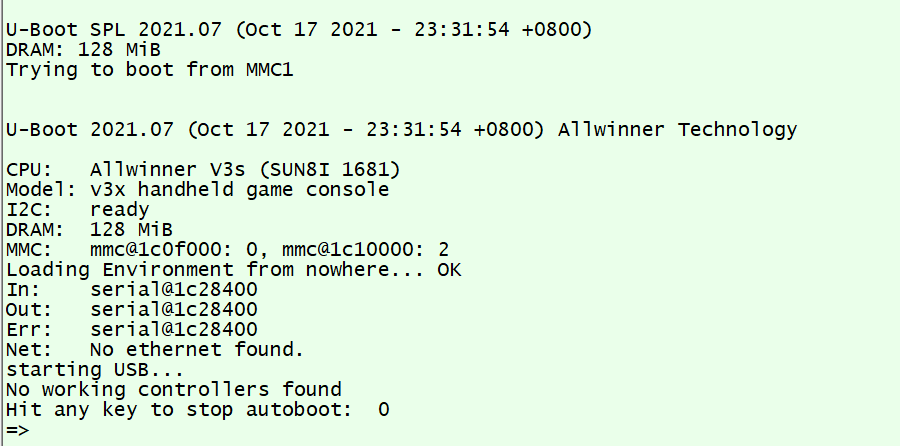
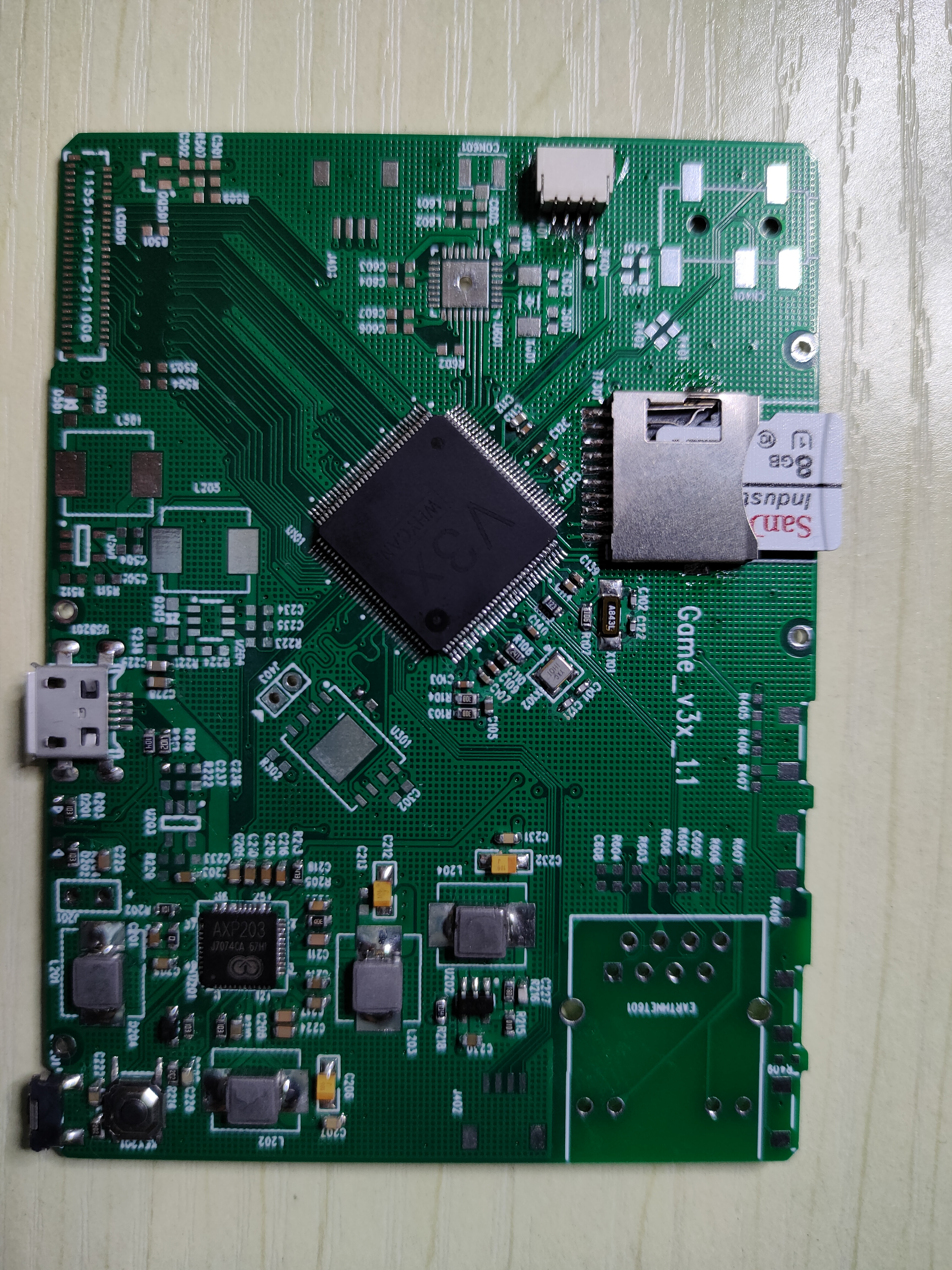
Game_V3x_V1.pdf
#25 Re: 全志 SOC » 刚刚收到的全志AIC800开发板,接个串口打印LOG 试一试 » 2021-09-09 19:41:40
AIC800又复活了?
#26 Re: 全志 SOC » [V3X][Mystery]项目开发进度汇报 » 2021-08-21 10:19:08
芯片哪搞啊,万能宝木有啊
晕哥在小黄鱼有卖,买了两片还送了我一块F1C600的板子:D
#27 Re: 全志 SOC » 计划做一个AIC800的超小HMI工控开发板,开源原理图封装库和layout的那种 » 2021-08-18 13:53:33
@linstar
在哪找的芯片,做的怎么样了?
#28 Re: 全志 SOC » 计划做一个AIC800的超小HMI工控开发板,开源原理图封装库和layout的那种 » 2021-02-19 18:18:07
qianniao29 说:看论坛里讨论的ssd202还不错,至少能买到
不是一个东西 这个64位的arm 那个是A7
性能强是强,但对于DIY玩家来说太难买了。已公司名字另当别论
#29 Re: 全志 SOC » 计划做一个AIC800的超小HMI工控开发板,开源原理图封装库和layout的那种 » 2021-02-08 11:35:24
看论坛里讨论的ssd202还不错,至少能买到
#30 Re: 全志 SOC » 计划做一个AIC800的超小HMI工控开发板,开源原理图封装库和layout的那种 » 2021-02-03 10:40:01
这个芯片在哪边能买到?淘宝上都搜不到
#31 Re: Cortex M0/M3/M4/M7 » 开源小小草科技的基于STM32H7的小掌机,PCB和源码都有哦 » 2020-07-10 15:21:38
支持一下楼主的开源精神,想仿造一个自己玩
页次: 1
- 首页
- » 搜索
- » qianniao29 发表的帖子