- 首页
- » 搜索
- » 我就是废物 发表的帖子
页次: 1
#1 Qt/MSVC/MINGW/C++/MFC/GTK+/Delphi/BCB » 解决 QSslSocket::connectToHostEncrypted: TLS initialization failed 问题 » 2020-12-29 15:07:12

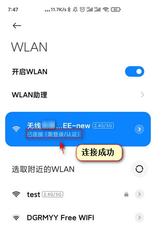
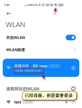
#4 DIY/综合/Arduino/写字机/3D打印机/智能小车/平衡车/四轴飞行/MQTT/物联网 » 请问公共场所这种共享WIFI热点是什么原理?在小米手机的WIFI连接页面可以看到是否需要登录,是否已登录 » 2020-09-22 10:29:42
#5 Re: 全志 SOC » Widora TINY200 R2 体验版开源开发包,修复了大部分F1C100s/F1C200s的遗留问题 » 2020-08-12 16:37:30
哦……你看一下board/widora/tiny200/devicetree/uboot/suniv-f1c100s-generic.dts
SPI总线上是不是配了SPI-NAND这个错误是SPI-NAND驱动抛出来的
果然是 compatible = "spi-nand";
...

&spi0 {
        pinctrl-names = "default";
        pinctrl-0 = <&spi0_pins_a>;
        status = "okay";

        flash@0 {
                #address-cells = <1>;
                #size-cells = <1>;
                // compatible = "winbond,w25q128", "jedec,spi-nor";
                compatible = "spi-nand";
                reg = <0>;
                spi-max-frequency = <40000000>;
        };
};
....#7 Re: 全志 SOC » Widora TINY200 R2 体验版开源开发包,修复了大部分F1C100s/F1C200s的遗留问题 » 2020-08-12 15:43:48
U-Boot SPL 2020.07 (Aug 10 2020 - 20:16:18 +0800)
DRAM: 64 MiB
Trying to boot from MMC1
Card did not respond to voltage select!
spl: mmc init failed with error: -95
Trying to boot from MMC2
Card did not respond to voltage select!
spl: mmc init failed with error: -95
Trying to boot from sunxi SPI


U-Boot 2020.07 (Aug 10 2020 - 20:16:18 +0800) Allwinner Technology

CPU:   Allwinner F Series (SUNIV)
Model: Allwinner F1C100s Generic Device
DRAM:  64 MiB
MMC:   mmc@1c0f000: 0, mmc@1c10000: 1
Setting up a 480x272 lcd console (overscan 0x0)
In:    serial
Out:   vga
Err:   vga
Allwinner mUSB OTG (Peripheral)
starting USB...
No working controllers found
Hit any key to stop autoboot:  0
Card did not respond to voltage select!
Card did not respond to voltage select!
starting USB...
No working controllers found
USB is stopped. Please issue 'usb start' first.
=>
spi flash 固件sysimage-flash.img有一点点bug, 可能这个u-boot打包的是TF卡版本的。
#11 Re: DIY/综合/Arduino/写字机/3D打印机/智能小车/平衡车/四轴飞行/MQTT/物联网 » V3s控制GPIO扩展芯片 NXP PCF8574, 可以读IO电平,但是怎么也写不了低电平,请各位大佬帮我瞅瞅 » 2020-07-02 10:02:09
借助逻辑分析仪,终于找到原因了, 重新配置dts:
        pcf8574: gpio@20 {
                compatible = "nxp,pcf8574";
                reg = <0x20>;
                gpio-controller;
                #gpio-cells = <2>;
                interrupt-controller;
                #interrupt-cells = <2>;
        };
原来我是从 别 处 粘贴 过来的:
compatible = "nxp,pcf8575";
根据驱动源码: https://github.com/torvalds/linux/blob/master/drivers/gpio/gpio-pcf857x.c
static const struct i2c_device_id pcf857x_id[] = {
{ "pcf8574", 8 },
...
{ "pcf8575", 16 },
...
{ }
};
pcf8574 是8bit的, pcf8575是16bit的。
#13 Re: DIY/综合/Arduino/写字机/3D打印机/智能小车/平衡车/四轴飞行/MQTT/物联网 » V3s控制GPIO扩展芯片 NXP PCF8574, 可以读IO电平,但是怎么也写不了低电平,请各位大佬帮我瞅瞅 » 2020-07-01 23:07:20
#14 Re: DIY/综合/Arduino/写字机/3D打印机/智能小车/平衡车/四轴飞行/MQTT/物联网 » V3s控制GPIO扩展芯片 NXP PCF8574, 可以读IO电平,但是怎么也写不了低电平,请各位大佬帮我瞅瞅 » 2020-06-30 22:46:43
#15 Re: DIY/综合/Arduino/写字机/3D打印机/智能小车/平衡车/四轴飞行/MQTT/物联网 » V3s控制GPIO扩展芯片 NXP PCF8574, 可以读IO电平,但是怎么也写不了低电平,请各位大佬帮我瞅瞅 » 2020-06-30 22:14:17
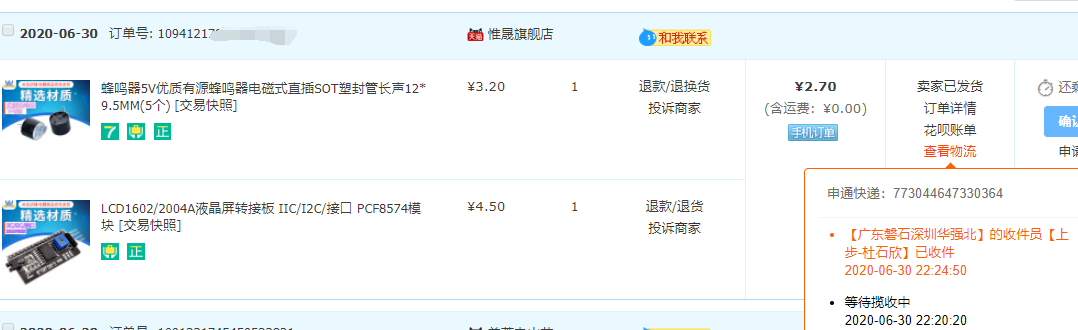
先暂停再下单买一个, 改天继续折腾: https://detail.tmall.com/item.htm?id=600629589545
#16 Re: DIY/综合/Arduino/写字机/3D打印机/智能小车/平衡车/四轴飞行/MQTT/物联网 » V3s控制GPIO扩展芯片 NXP PCF8574, 可以读IO电平,但是怎么也写不了低电平,请各位大佬帮我瞅瞅 » 2020-06-30 21:42:06
接LED也控制不了, 有点怀疑芯片是坏的: https://whycan.cn/t_4669.html#p48259
#17 DIY/综合/Arduino/写字机/3D打印机/智能小车/平衡车/四轴飞行/MQTT/物联网 » V3s控制GPIO扩展芯片 NXP PCF8574, 可以读IO电平,但是怎么也写不了低电平,请各位大佬帮我瞅瞅 » 2020-06-30 11:52:11
- 我就是废物
- 回复: 13
### 安装驱动
# modprobe gpio-pcf857x
[ 2380.235831] pcf857x 0-0020: probed
#
# echo 400 > /sys/class/gpio/export

# echo low > /sys/class/gpio/gpio400/direction
# echo 0 > /sys/class/gpio/gpio400/value
# echo 1 > /sys/class/gpio/gpio400/value
这样, P0还是输出 3V3,始终不能输出 0V
# echo out > /sys/class/gpio/gpio400/direction
# echo 0 > /sys/class/gpio/gpio400/value
# echo 1 > /sys/class/gpio/gpio400/value
low改为out或者high也是一样不能输出低电平
接着我在P0加10K下拉电阻,无论怎么控制都是输出2.7V。
# echo in > /sys/class/gpio/gpio400/direction
# cat /sys/class/gpio/gpio400/value
输入功能正常。
百思不得其解, 请各位路过的大神指导。
#18 Re: 全志 SOC » F1C200S PDA手持机调试 » 2020-06-24 11:21:08
https://e2e.ti.com/support/processors/f/791/t/516807?AM335x-MMC-CD-does-not-send-interrupt
[ 0.653431] gpiochip_find_base: found new base at 504
[ 0.653743] GPIO line 504 (reset_fg_i2c_mux) hogged as output/high
[ 0.653922] gpiochip_add: registered GPIOs 504 to 511 on device: pcf8574
[ 0.653943] pcf857x 0-0020: probed
[ 0.654413] gpiochip_find_base: found new base at 496
[ 0.654580] gpiochip_add: registered GPIOs 496 to 503 on device: pcf8574
[ 0.654597] pcf857x 0-0021: probed
[ 0.655050] gpiochip_find_base: found new base at 488
[ 0.655223] gpiochip_add: registered GPIOs 488 to 495 on device: pcf8574
[ 0.655238] pcf857x 0-0022: probed
[ 0.655692] gpiochip_find_base: found new base at 480
[ 0.655852] gpiochip_add: registered GPIOs 480 to 487 on device: tca9554
[ 0.655867] pcf857x 0-0070: probed
https://github.com/torvalds/linux/blob/master/drivers/gpio/gpiolib.c
	/* From this point, the .release() function cleans up gpio_device */
	gdev->dev.release = gpiodevice_release;
	dev_dbg(&gdev->dev, "registered GPIOs %d to %d on %s\n", gdev->base,
gdev->base + gdev->ngpio - 1, gdev->chip->label ? : "generic");#19 Re: 全志 SOC » F1C200S PDA手持机调试 » 2020-06-24 10:10:11
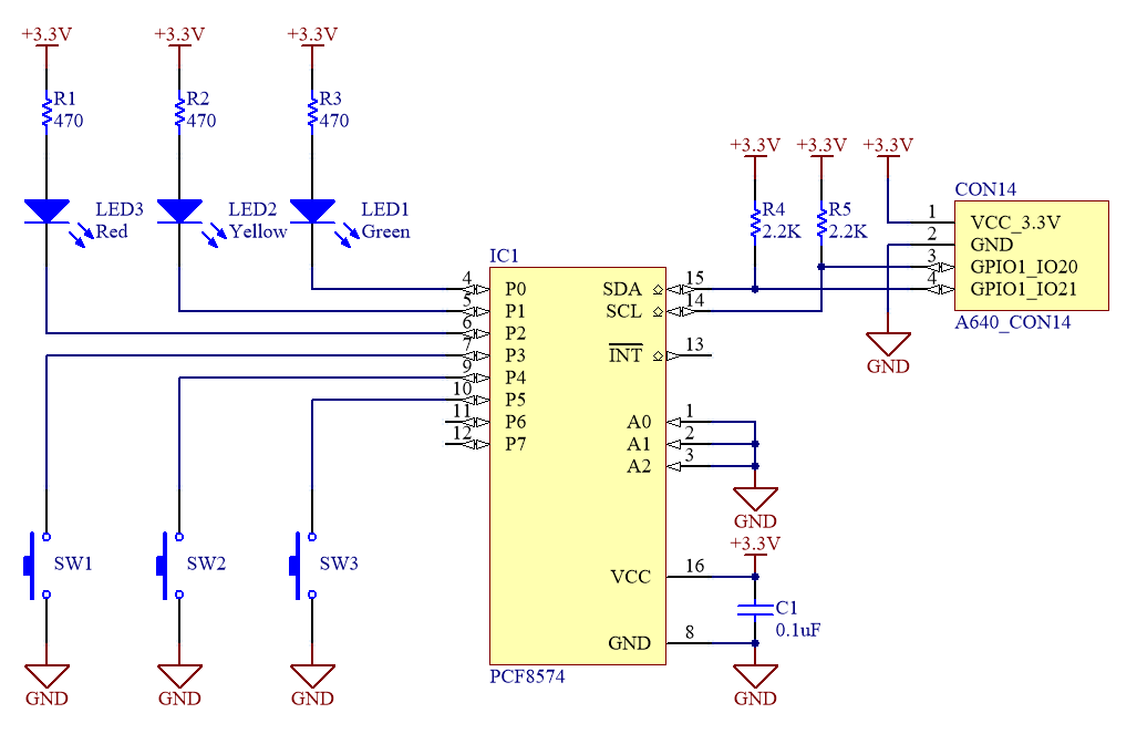
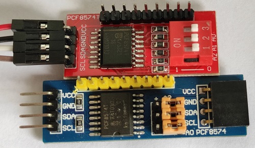
5.3。使用I / O扩展器(PCF8574)
在这里,我们将向您展示如何将I / O扩展器连接到I 2 C总线。
使用的设备是:
PCF8574(由恩智浦半导体公司制造)
这次使用的PCF8574具有以下功能。
单电源供电(2.5-6V)
I 2 C连接(标准模式)
地址0x20至0x27(8个可以连接到同一总线)
GPIO数量8
无需设置I / O方向
具有输入更改中断功能
表示与Armadillo-640的连接。从Armadillo-640的CON14将PCF8574连接到I2C4。指定地址的A0至A2全部连接到GND [ 12 ]。例如,连接了开关和LED。输入低时,开关应打开;输出低时,LED灯应点亮。
5.3.2。创建支持的内核映像
创建启用了PCF8574驱动程序的DTB和Linux内核。
请按照以下步骤更改标准内核的源代码。
编辑设备树
在内核配置中启用设备驱动程序
构建内核和DTB并写入Armadillo
首先,创建一个设备树。文件名是arch / arm / boot / dts / armadillo-640-i2c4.dtsi:
&iomuxc {
        pinctrl_i2c4: i2c4grp {
                fsl,pins= <
                        MX6UL_PAD_UART2_TX_DATA__I2C4_SCL 0x40010808
                        MX6UL_PAD_UART2_RX_DATA__I2C4_SDA 0x40010808
                >;
        };
};

&i2c4 {
        status = "okay";
        clock-frequency = <50000>;
        pinctrl-names = "default";
        pinctrl-0 = <&pinctrl_i2c4>;

        pcf8574@20 {                            // 1
                #address-cells = <2>;
                #size-cells = <0>;
                compatible = "nxp,pcf8574";
                reg = <0x20>;                   // 2
                gpio-controller;
                #gpio-cells = <2>;
        };
};
make menuconfig 配置驱动:
Device Drivers  --->
  -*- GPIO Support  --->
    I2C GPIO expanders  --->
          [*] PCF857x, PCA{85,96}7x, and MAX732[89] I2C GPIO expanders   ← 有効にする
首先,创建GPIO类目录:
[armadillo ~]# ls /sys/class/gpio/
export     gpiochip128  gpiochip504  gpiochip96
gpiochip0  gpiochip32   gpiochip64   unexport
[armadillo ~]# echo 504 > /sys/class/gpio/export
[armadillo ~]# echo 505 > /sys/class/gpio/export
[armadillo ~]# echo 506 > /sys/class/gpio/export
[armadillo ~]# echo 507 > /sys/class/gpio/export
[armadillo ~]# echo 508 > /sys/class/gpio/export
[armadillo ~]# echo 509 > /sys/class/gpio/export
[armadillo ~]# echo 510 > /sys/class/gpio/export
[armadillo ~]# echo 511 > /sys/class/gpio/export
[armadillo ~]# ls /sys/class/gpio/
export   gpio506  gpio509  gpiochip0    gpiochip504  unexport    ←gpio504~gpio511が作成された
gpio504  gpio507  gpio510  gpiochip128  gpiochip64
gpio505  gpio508  gpio511  gpiochip32   gpiochip96
[armadillo ~]# cat /sys/class/gpio/gpio504/direction
in                                                               ←初期状態では入力
接下来,让我们实际访问PCF8574的GPIO并打开LED:
[armadillo ~]# cat /sys/class/gpio/gpio504/direction
in                                                               ←初期状態では入力
[armadillo ~]# echo high > /sys/class/gpio/gpio504/direction     ←highに設定してもLED1は消灯のまま
[armadillo ~]# echo low > /sys/class/gpio/gpio504/direction      ←lowに設定するとLED1が点灯
[armadillo ~]# echo 1 > /sys/class/gpio/gpio504/value            ←1に設定するとLED1が消灯
[armadillo ~]# echo 0 > /sys/class/gpio/gpio504/value            ←0に設定するとLED1が点灯
最后,让我们获取开关的状态:
[armadillo ~]# cat /sys/class/gpio/gpio505/value                 ←スイッチがONの時に実行
0
[armadillo ~]# cat /sys/class/gpio/gpio505/value                 ←スイッチがOFFの時に実行
1#20 Re: 全志 SOC » F1C200S PDA手持机调试 » 2020-06-24 10:01:14
中断在 dts 配置即可:
参考: https://whycan.cn/t_3381.html#p29908
gpio驱动: https://github.com/torvalds/linux/blob/master/drivers/gpio/gpio-pcf857x.c
dts配置: https://github.com/torvalds/linux/blob/master/Documentation/devicetree/bindings/gpio/gpio-pcf857x.txt
keyboard驱动: https://github.com/torvalds/linux/blob/master/drivers/input/misc/pcf8574_keypad.c
#21 Re: 全志 SOC » V3s Linux SPI NOR FLASH 读写速度测试 » 2020-06-22 15:26:57
#22 Re: 全志 SOC » V3s Linux SPI NOR FLASH 读写速度测试 » 2020-06-22 15:22:11
#23 Re: 全志 SOC » V3s Linux SPI NOR FLASH 读写速度测试 » 2020-06-22 11:13:26
# date;dd if=/dev/mtd6 of=/dev/null bs=1M;date;
Thu Jan  1 00:01:03 UTC 1970
32+0 records in
32+0 records out
Thu Jan  1 00:01:07 UTC 1970
#
#
# date;dd if=/dev/mtd6 of=/dev/null bs=16M;date;
Thu Jan  1 00:00:51 UTC 1970
2+0 records in
2+0 records out
Thu Jan  1 00:00:55 UTC 1970
设备树配置SPI 频率 80Mhz, bs配置1M/16M, 时间都是4秒, 粗算读速度 8MB/s
#24 Re: 全志 SOC » V3s Linux SPI NOR FLASH 读写速度测试 » 2020-06-22 11:02:51
#25 全志 SOC » V3s Linux SPI NOR FLASH 读写速度测试 » 2020-06-22 10:49:57
- 我就是废物
- 回复: 4
设备树配置SPI 频率 50Mhz:
&spi0 {
        status ="okay";

        mx25l25635e:mx25l25635e@0 {
                compatible = "jedec,spi-nor";
                reg = <0x0>;
                spi-max-frequency = <50000000>;
                #address-cells = <1>;
                #size-cells = <1>;
        };

};
测试 MX25L512 末32M分区读速度:
默认块大小读
# date;dd if=/dev/mtd6 of=/dev/null;date;
Thu Jan 1 00:05:20 UTC 1970
65536+0 records in
65536+0 records out
Thu Jan 1 00:05:30 UTC 1970
bs采用默认值, 读速度32/10 = 3.2M/s
# date;dd if=/dev/mtd6 of=/dev/null bs=1M;date;
Thu Jan 1 00:15:00 UTC 1970
32+0 records in
32+0 records out
Thu Jan 1 00:15:06 UTC 1970
bs调整到1M, 读速度 32/6 = 5.3MB/s
页次: 1
- 首页
- » 搜索
- » 我就是废物 发表的帖子